
This guide follows 55 talks on quantum control at IEEE Quantum Week 2026 in Toronto. Many of them raced one deadline, the few millionths of a second that error correction allows.
On the evening of Sunday 13 September, Gilad Ben-Shach of Quantum Machines gave the week’s first keynote and started a stopwatch. It ran through every later talk on control and qubit calibration. A measurement must be decoded and a fix sent back to the qubits within about 10 microseconds, Ben-Shach said. A slower loop lets error correction fall behind. From then on, every maker of control boxes in Toronto was in effect racing that clock, from the big vendors to the national labs that give their designs away.
A quantum processor cannot do anything on its own. It is a small chip in a ring of ordinary electronics, and those racks turn each gate into a shaped pulse of microwaves, laser light or voltage. The timing has to be right to within billionths of a second, across hundreds of channels at once, and the same racks must read the answers back. Qubits drift, too. The pulses that worked this morning may be wrong by the afternoon.
Taken together, the 55 talks followed here suggest that the stopwatch, more than the qubit, now sets the design of the controller. They also suggest that the makers are beating it on paper faster than anyone is timing them on real qubits. The race was crowded. Quantum Machines sent decoding jobs to an NVIDIA GPU and back, Qblox paired its controller with Riverlane’s decoder, and Berkeley Lab’s QubiC and Maryland’s RISC-Q closed a loop faster still.
The strongest objection is that the stopwatch is the easier problem. On Thursday morning Yuval Baum of Q-CTRL said a machine that calibrates 23 hours a day while week-long error-correction jobs wait is unworkable. Shane Caldwell of NVIDIA said today’s machines already go offline several times a day. On that view the hard part is keeping a large chip tuned at all. Speed comes second. The objection has real force, because a machine that is offline for retuning has no feedback loop to time, however fast its electronics might be.
Yet calibration and the stopwatch turned out to be the same contest, because both move work out of the host computer and into the box beside the fridge. Qblox moved a full single-qubit tune-up onto its controller, and it ran nearly twenty times faster. Once the box does the work, the question becomes who owns the box. Fermilab’s QICK and Berkeley Lab’s QubiC are the open designs, while vendors sell their own, and Monday’s workshop panel voted that one control stack for every qubit type is a myth.
Whoever builds the box that closes the loop will hold a strong hand over every qubit maker, because every qubit, whatever it is made of, has to send its readings through that box and wait for the fix. The weak point is how much of this racing happened without any qubits at all. Simulators, loopback cables and synthetic error data carried most of the headline numbers, and few of them were timed on a chip. The largest hardware results, from HRL’s silicon spins and Atom Computing’s neutral atoms, came from firms that build their own machines. Most laps so far were run on an empty track.
What it is. Quantum control is the electronics and software that turn a quantum program into timed pulses, read the qubits back and keep them tuned. Error correction adds a deadline of a few microseconds for every round.
What QCE26 showed. Quantum Machines, Qblox, Berkeley Lab and NVIDIA all showed feedback loops of a few microseconds or less. NVIDIA’s NVQLink, which lets a GPU join the loop, appeared in at least five talks.
The calibration shift. Qblox ran a single-qubit tune-up on its controller in 286 milliseconds, against 5,520 the usual way. Several groups proposed ways to recalibrate only when needed.
The caution. Most loop times came from emulated qubits, loopback cables or synthetic data. Most hardware runs used a few qubits, and the two large ones, at HRL and Atom Computing, came from firms that build their own machines.
Racing the error-correction stopwatch
Error correction needs a loop that reads helper qubits, works out what went wrong and sends back a fix before the qubits lose their state. Nine talks went at that loop from the controller side, and most of them timed it without a chip attached.
Quantum Machines sets a 10 microsecond budget
Gilad Ben-Shach of Quantum Machines called their firm the largest in quantum control, with more than 400 customers. Its main box runs about a thousand timed channels at room temperature. Citing a 2024 paper, Ben-Shach said that to factor the number 21 with full error correction takes 1,015 noisy qubits and almost 400,000 gates, so speed counts at every step. Ben-Shach’s budget for the loop was 10 microseconds.
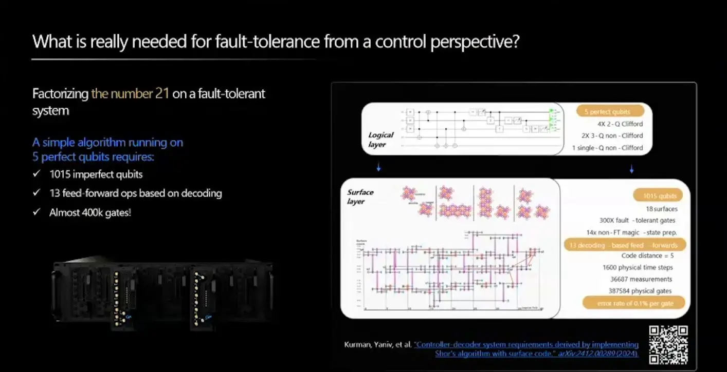
Their timing plot, run on simulated data, sent about 20 percent of decoding jobs to an NVIDIA Grace Hopper machine, where they took 5.70 microseconds on average. The rest cleared inside the box in 472 nanoseconds. Shane Caldwell of NVIDIA then took the stage to describe NVQLink, a link any vendor can add so a GPU can decode errors and correct drift while a circuit runs. Round trips into a live GPU ran at 3.76 microseconds.
Qblox moves calibration onto the controller
Francesco Battistel, who leads the roadmap at Qblox, sorted the jobs of a control stack by deadline, from under a microsecond to reset a qubit to about 10 microseconds for a decoder. Battistel’s main result was a single-qubit tune-up. It took 5,520 milliseconds the usual way and 286 when each step fed the next on the board itself, nearly twenty times faster.
For error correction, Qblox paired its Cluster with Riverlane’s Deltaflow 2 decoder. With emulated qubits fed synthetic error data, the time from last check to correction ran from 6.37 microseconds for a small code to 11.37 for a larger one. Qblox’s own share was just over 1 microsecond, and the decoder took the rest.
Qblox’s chief executive says calibration can stay flat
Niels Bultink, chief executive and co-founder of Qblox, gave Thursday’s keynote. Bultink argued that a quantum processor is the qubit chip plus all the control, calibration and decoding hardware around it, and that buyers should judge the whole package. A qubit has 50 to 100 settings to tune, Bultink said, so a 10,000-qubit machine carries about a million. A 100-qubit system, Bultink said, carries about 600 small processor cores.
Bultink claimed calibration time stays flat as qubits are added, because each core fits its own data in parallel. Its LINQ link gives feedback in about 600 nanoseconds. Bench runs with Riverlane’s decoder took about 7 to 10 microseconds. Those were bench runs, and Bultink said the next step is a deployment with Oxford Quantum Circuits in a data centre, aimed at logical qubits corrected in real time.
QubiC closes a loop in 446 nanoseconds
Gang Huang of Lawrence Berkeley National Laboratory presented QubiC for its team. QubiC 2.0 runs on an AMD board and drives several kinds of superconducting qubit, and it gives each qubit its own small processor core so that each one can follow its own program. The largest build links six chassis. Machine learning already runs on the chip to sort readouts into 0 and 1.
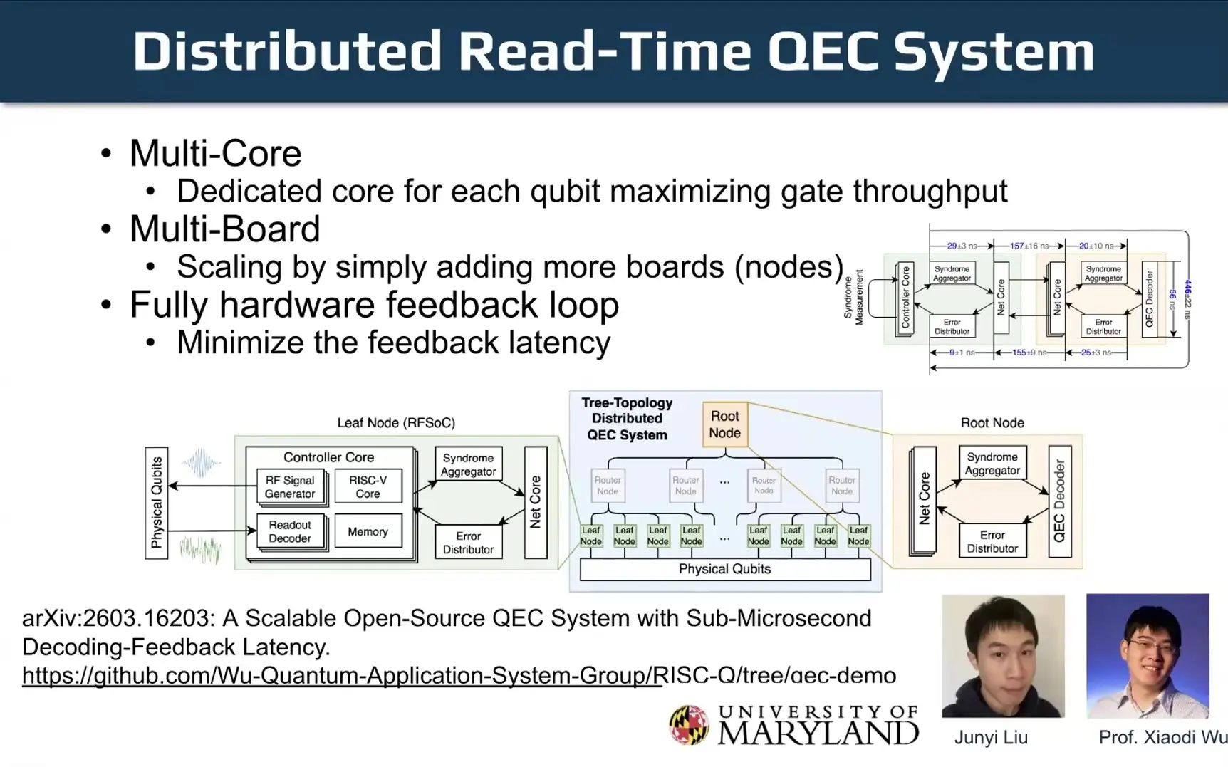
Huang reported an 80 nanosecond round trip between two boards and 4 microseconds to an NVIDIA DGX Spark. With Xiaodi Wu’s group at the University of Maryland and its RISC-Q processor, a tree of boards closed the decoding and feedback loop in 446 nanoseconds. Wu’s own paper, later in the week, timed that loop with the signal looped back in place of a chip. The design is free. A team member is starting a company to sell boards.
Tennessee refuses stale corrections
Charles Cao of the University of Tennessee, Knoxville presented DART-Q, written with Sergei Kalinin, which won a best-paper award in the QNET track. In a machine built from modules, a measurement on one module can decide a fix on another, and that fix has to land before the qubits decay. A fix can fire a pulse or simply be logged. Cao said the controller must pick the right one or refuse.
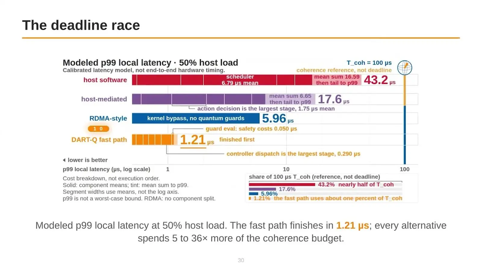
DART-Q tags each event and rejects stale ones. In tests, 280,000 events with full guards gave zero wrong actions, and a model put the slowest one percent of delays at 43.2 microseconds for host software against 1.21 for DART-Q’s fast path. The switch does not yet drive a quantum computer live. On IBM’s ibm_fez, logging the fix scored 0.942 average fidelity against 0.928 for real pulses.
Munich adds vector instructions for qubits
Xiaorang Guo of the Technical University of Munich presented HiSEP-Q 2.0, written with Kun Qin, Yanbin Chen, Carsten Trinitis and Martin Schulz. On superconducting qubits, a long stream of instructions that each touch one qubit can use up the time the qubits stay coherent. Guo’s design lets one instruction cover many qubits at once. Four new instructions sit on an unchanged RISC-V core.
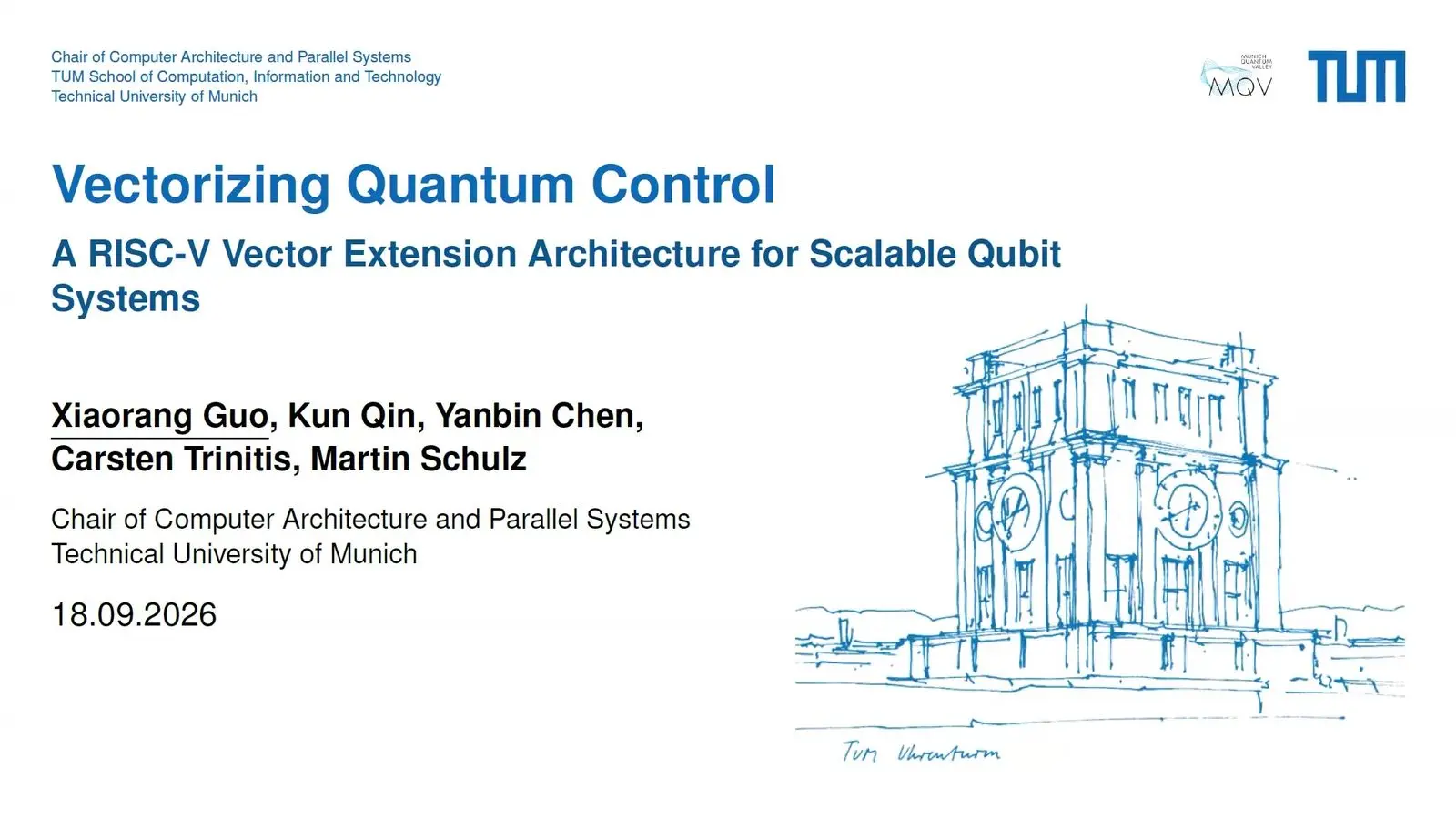
One register reaches 16 qubits and eight reach 128. On 12 standard test circuits the mean speed-up over Guo’s own earlier version was 1.26, larger for parallel work and small for circuits that run one step after another. That earlier version was the only baseline.
NVIDIA puts the wait on the decode and the next step
Justin Lietz, who works on error correction at NVIDIA, timed a decode in software on Quantinuum’s Helios. The median was 67 microseconds. The link added about 2 microseconds each way, and a hop over plain 100 gigabit Ethernet, with no host processor in the path, averaged 3.84 microseconds and never took more than 3.96. So the link was the small part. Most of the wait went on the decode and on working out the next step.
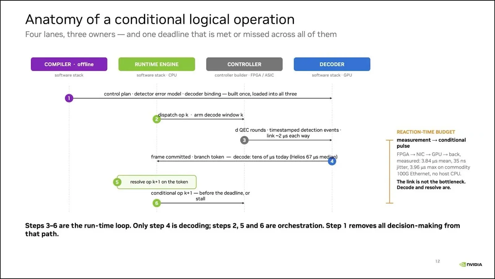
Lietz built programs with CUDA-Q Logical, a compiler that breaks a program into gadgets, circuits and a control plan, and then ran one with eight logical qubits on Helios. It used about 30 data qubits and 20 helpers. The shot came back inside a budget of about 2 milliseconds, and Lietz said the decoder made it better.
Asked how a machine built as one piece and an open stack can share parts, Lietz said the line between hardware and software should rise as a device grows up. While the choice of code is still open, it should stay low.
Qblox closes a distance-9 decoding loop in about 10 microseconds
Niels Bultink, chief executive and founder of Qblox, set out the firm’s stack on Tuesday, two days before the keynote above. Qblox now reaches three nines for gates and readout on most platforms, Bultink said. A full single-qubit calibration takes about a quarter of a second once the loops run in the sequencer cores on the board itself. Checks run on every qubit at once.
Qblox streams error data at 2 gigabits per second, which Bultink said is enough for chips of 2,000 to 10,000 qubits, and with Riverlane a desktop test of a distance-9 code closed its round trip in about 10 microseconds. The decoder took most of that time. A link through NVQLink to NVIDIA’s small DGX Spark reached about 7 microseconds.
RISC-Q builds a controller from a tenth of QICK’s code
Xiaodi Wu of the University of Maryland presented RISC-Q, which builds control hardware from a short list of settings, the way tools such as Chisel build RISC-V chips. It copies the open QICK and QubiC designs with about a tenth of QICK’s code. Programs in OpenQASM 3 become C. One AMD radio chip holds 30 signal generators, or about 14 qubits a board when readout lines are shared.
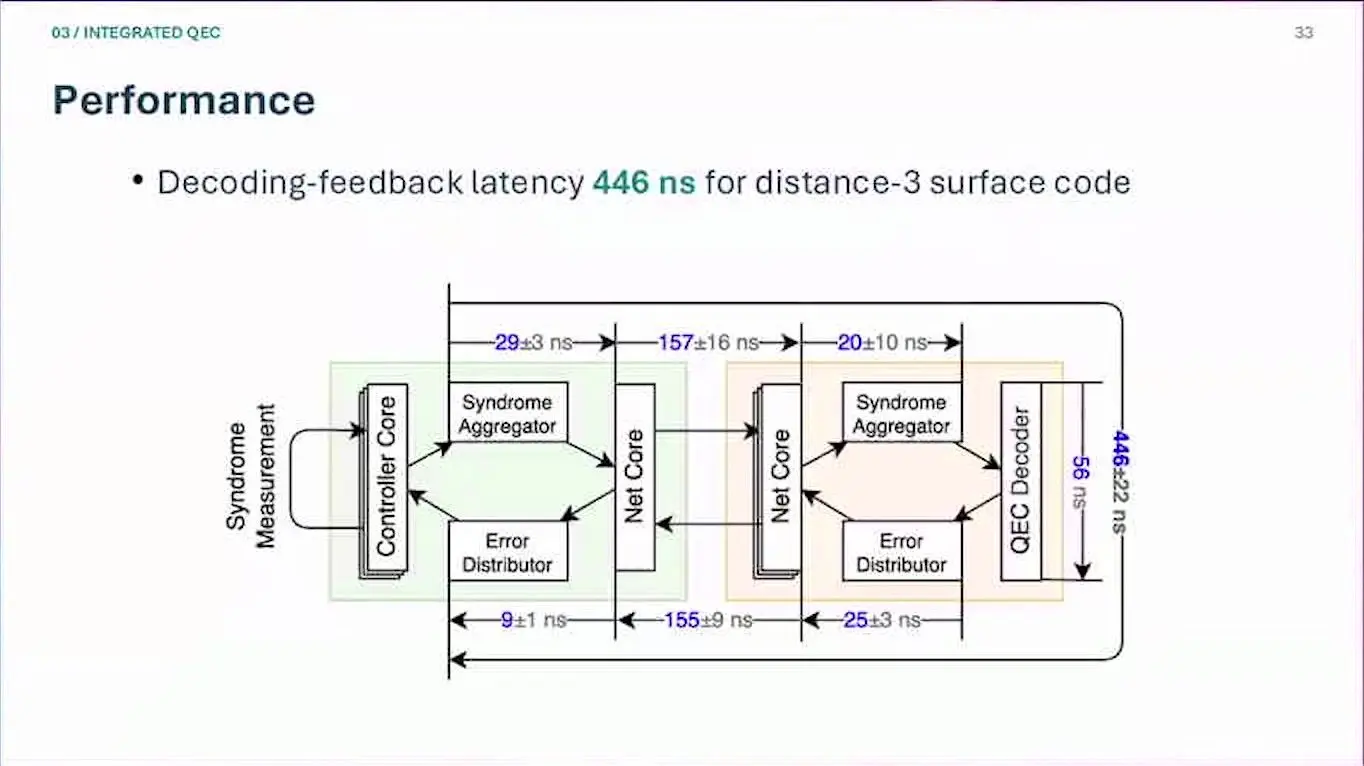
With Berkeley Lab, the group built the loop that Gang Huang described, on a tree of boards that talk in about 150 nanoseconds and a decoder in hardware. Tested in loopback with no qubits, the loop took 446 nanoseconds from collecting the checks to sending the fix, for a distance-three surface code. No chip was attached. Wu put distance 21 at about a microsecond.
Another tool builds decoders from a written spec. By Wu’s account these message-passing decoders run at a slightly faster clock than the one IBM built by hand on an FPGA for its Relay-BP decoder. Wu said the tree suits systems of up to about 1,000 qubits.
Calibration that never stops
Qubits drift, and a full calibration takes them offline. Seven talks asked when a machine should stop to retune, and how to make retuning cheap enough to do all the time.
Texas moves logical qubits away from drifting hardware
Maxwell Poster, a PhD student at the University of Texas at Austin, presented EDIQT with Jason Chadwick and Jonathan Baker. The setting is the surface code, which spreads one logical qubit over a grid of physical ones, and the usual daily tune-up takes the whole grid offline while it runs. Poster called that wasteful. The qubits can do nothing else.
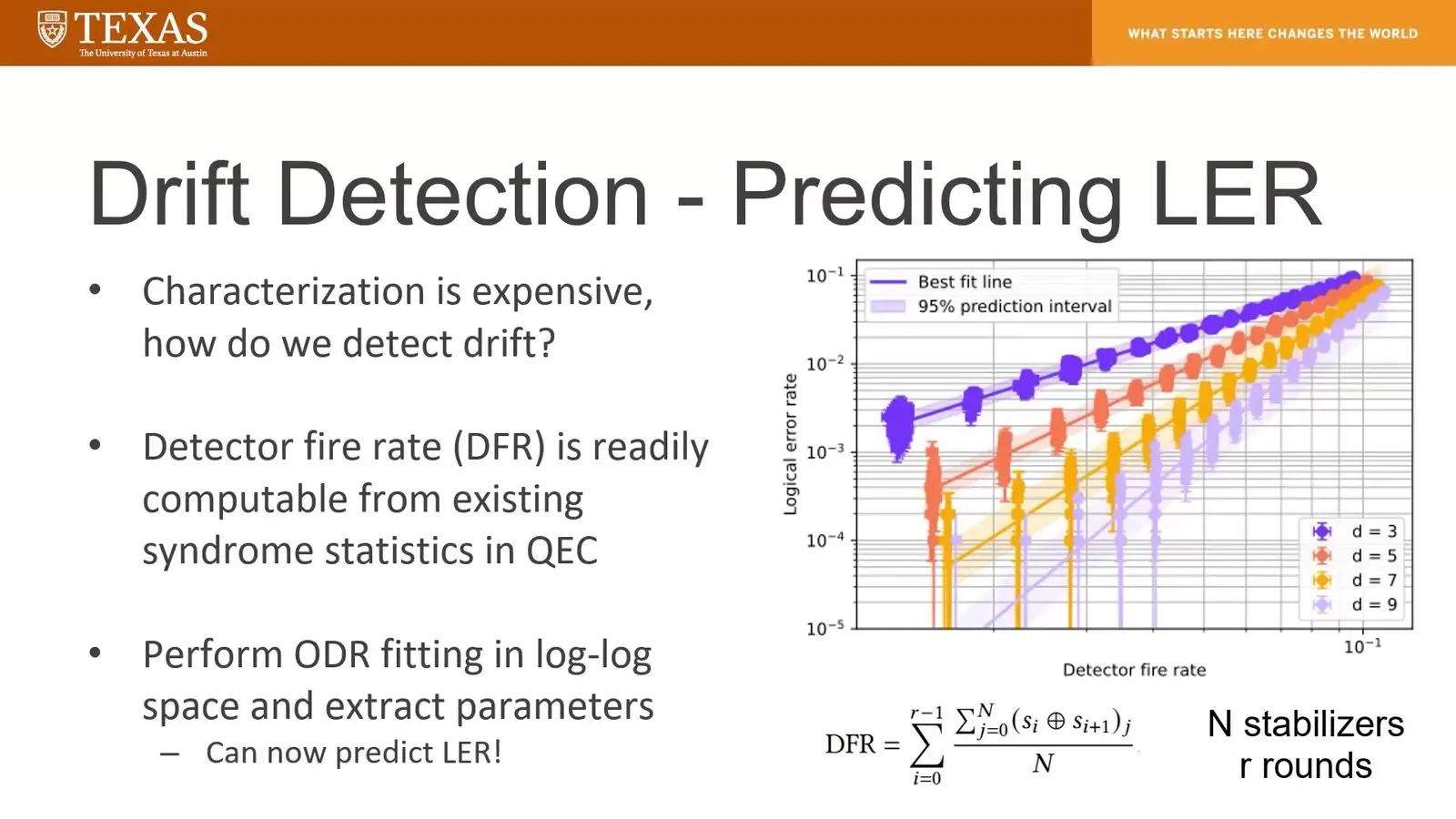
Their signal is how often the code’s error checks fire. The decoder gets that number anyway, and in simulation it tracked the logical error rate closely. So EDIQT can move a logical qubit onto a spare tile before a set limit is crossed, and then retune the old tile while the work goes on next door. It all ran in simulation, with errors set to grow tenfold over about six hours.
LRZ decides when a hybrid job should pause
Xiaolong Deng of the Leibniz Supercomputing Centre in Garching asked when a running hybrid job should stop to recalibrate. Their centre calibrates its processors about once a day. Their model weighs how old the last calibration is, how far the result has drifted from its target, the time left and the hardware’s sensitivity. It then picks between carrying on, a light retune or a heavy one.

In a simulated job with three link speeds, a controller that looks six steps ahead beat the best fixed schedule in 0, 30 and 44 of 55 settings as the link got faster. Deng said the gain appears only when drift, calibration cost and the job’s pace sit on similar time scales. Deng said the model describes behaviour without the physics underneath and is not yet tied to hardware.
Dresden retunes a diamond chip only when needed
Sakineh Ghaderi spoke for a Dresden team with Abdelkrim Menina, Leon Röscher, Talía Lezama, Riccardo Bassoli and Frank Fitzek. Their data are 233 calibration snapshots taken over 10 days on a diamond chip that runs at room temperature, and each full calibration stops work for several minutes. They wanted to calibrate only when needed. Fewer stops mean more work done.

The room’s temperature explained almost none of the drift. On quiet days the spin still wandered by about 500 kilohertz. So the team replayed the data with a schedule that waits until a retune is needed, and that raised the work done by 3.6 percent over a fixed hourly plan while cutting calibrations by 45 percent. Fidelity barely moved.
A panel says no centre will wait for calibration
Gilad Ben-Shach of Quantum Machines moderated Thursday’s panel with Yonatan Cohen of Quantum Machines, Gang Huang of Berkeley Lab, Shane Caldwell of NVIDIA and Yuval Baum of Q-CTRL. Cohen split calibration into bringing a chip up from scratch, retuning, tuning for best results and tuning inside a running program. Baum said no computing centre will accept a machine that needs 20 PhD students in the back room. Nor will it wait. One that calibrates 23 hours a day while week-long jobs queue is just as unworkable, Baum said.
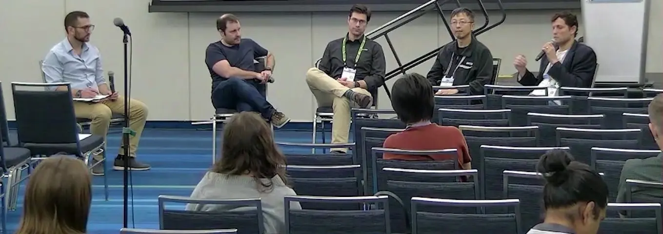
Caldwell said today’s machines go offline for about an hour two to four times a day, and that falling error rates shrink the room drift has to wander in. Caldwell described NVIDIA’s effort to shrink a calibration assistant from a frontier model down to one that runs on a single local GPU. The panel agreed retuning suits reinforcement learning. No one on stage showed a result.
Quantum Machines’ tutorial finds a readout resonator over the cloud
Kevin Villegas Rosales of Quantum Machines opened the tutorial whose second half follows. Attendees wrote code on their laptops and sent it through the cloud to a real qubit held near 10 millikelvin at the Israeli Quantum Computing Center. Every gate needs tuning, Villegas Rosales said. The box must know the frequency, voltage and pulse length that flip a qubit, and the custom has been to retune every six hours or so.
The hardware is an OPX1000 chassis. Its pulse processor, an FPGA running Quantum Machines’ own logic, changes a pulse within nanoseconds and runs loops and branches by itself. In the language QUA, commands such as measure, play and wait drive it, and a colleague from the customer team wrote a resonator sweep live, waiting 40 microseconds between shots for the resonator to empty.
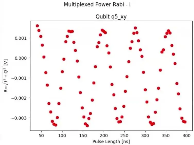
The plot showed a noisy background with one clear, narrow dip and a sharp turn in phase. That dip marks the readout resonator. It was enough, in the colleague’s view, to move on to gates, and the session set up a Rabi measurement, which lengthens the drive pulse until the qubit flips fully, for the second half to finish.
A tutorial tunes a real qubit in the cloud
In the second half of a Quantum Machines tutorial, attendees wrote QUA code in a browser and ran it on a real superconducting qubit at the IQCC. A Quantum Machines presenter led the exercises, and Songtian Sonia Zhang of Quantum Machines presented calibration graphs, in which small Python checks decide whether each step passed and what the next run should use. A measurement of the qubit’s lifetime gave a fitted 35,176 nanoseconds. The room had done three of about 15 steps in an hour.
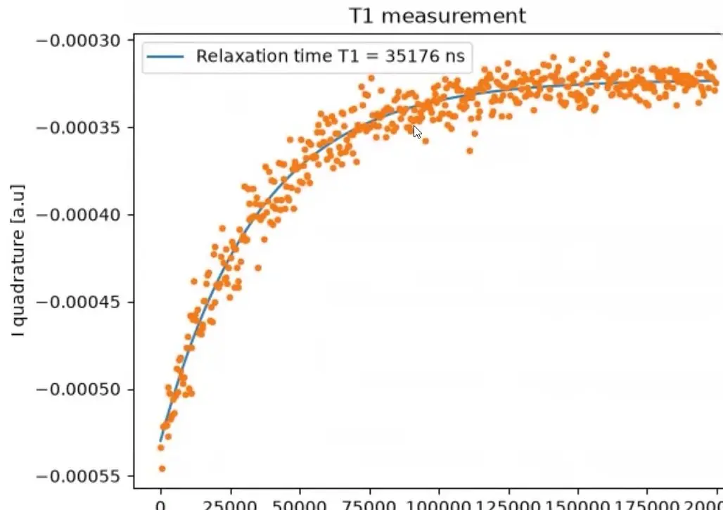
The last exercise ran a Bayesian estimate of the qubit’s lifetime inside the controller, updated after every shot. A paper from a group in Denmark reported the same answer in about 11 milliseconds, against about a second for a full curve. The live run settled near 35.6 microseconds after a retune, though the presenter said that any speed gain was hard to see through the delay of the cloud link to the lab. It ran all the same.
Quantum Machines slips calibration shots between user programs
Jonathan Reiner of Quantum Machines, who directs its product solutions, argued that calibration built on fixed graphs of experiments does not scale. It cannot keep up with drift. The firm’s answer is to slip short calibration shots in between the steps of the user’s own program, and to run them on the pulse processor inside its OPX controllers.
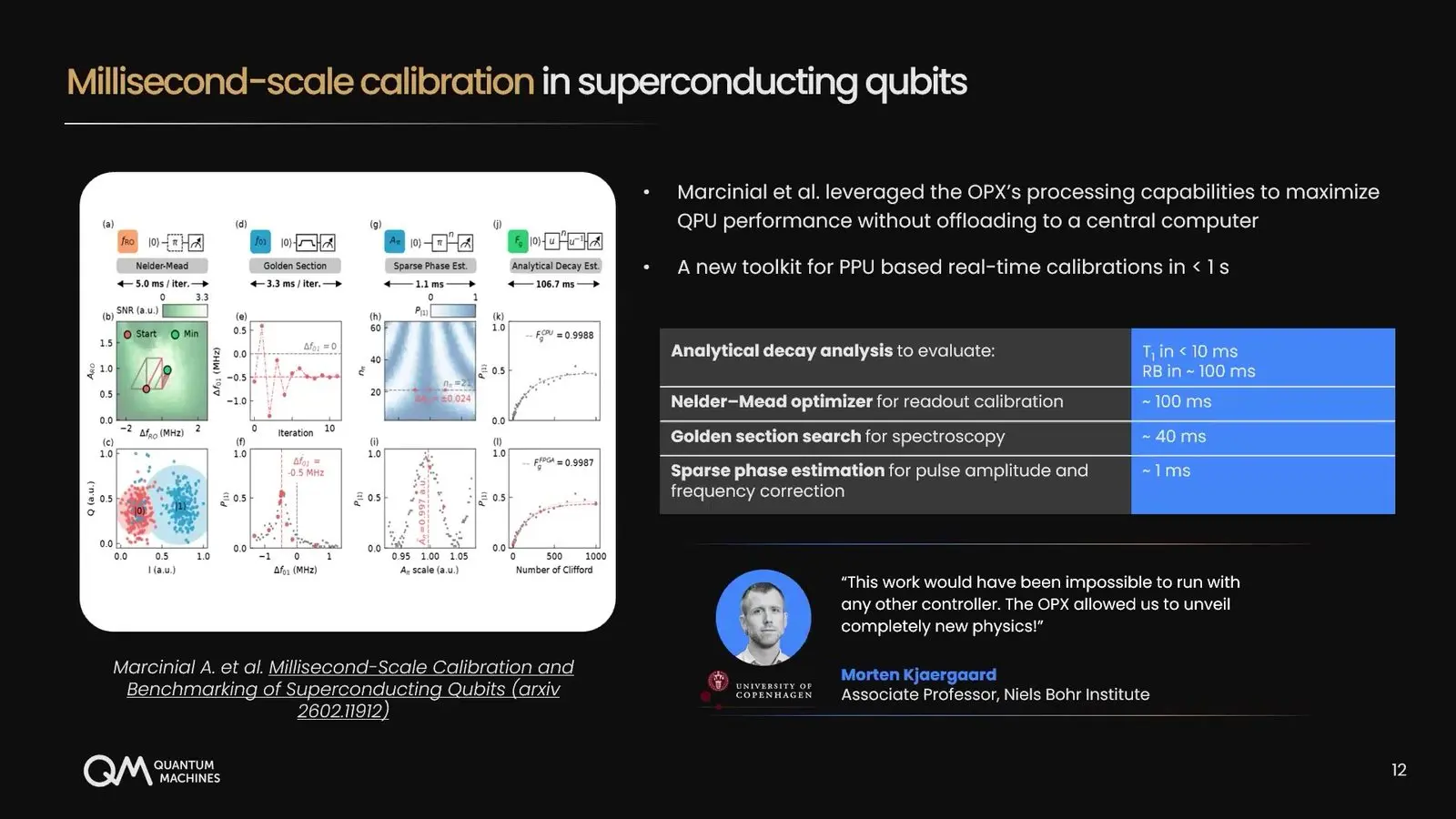
Reiner’s last example was a closed-loop method from Sandia, run inside a phase estimation program. It nudges a pulse’s strength after every shot, while a server resets the step size every five or ten shots, and the whole tune took about 100 milliseconds. Customers use the same idea. Ferdinand Kuemmeth’s spin-qubit lab tracks frequency with Bayesian updates, and the Niels Bohr Institute runs a full set of tune-ups in under a second.
For heavier jobs a link called OPNIC joins the controller to CPUs, GPUs and decoders such as Riverlane’s Deltaflow, with a design target of 10 to 20 microseconds. The same setup ran CUDA-Q on real qubits in Israel.
Open controllers and who owns the box
Much of the control world now runs on open designs from national laboratories. Nine talks and panels asked how far that openness should go, and who should own the box that results.
Fermilab’s QICK puts a full controller on one board
Fermilab’s QICK team ran the first half of a tutorial on its open-source controller, built on AMD’s RFSoC chip, which puts the processor, programmable logic and radio converters on one die. A member of the firmware team ran the notebooks with Sara Sussman and Gustavo Cancelo of Fermilab. QICK was built to cut the price of control electronics and to teach skills at the hardware level. Sussman counted 86 papers that use it.
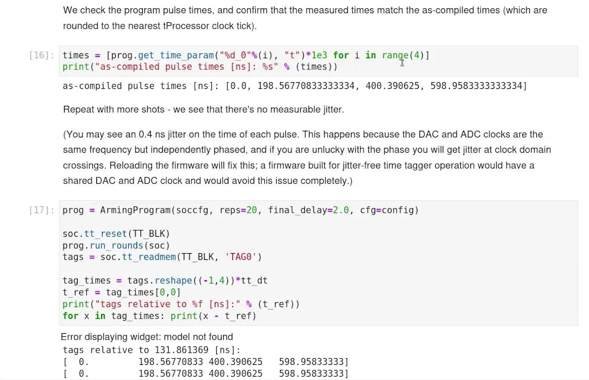
The live demo loaded firmware onto a board with 16 signal generators and 11 readout channels. Loopback cables sent pulses straight back to the inputs, and a time tagger matched the compiled pulse times on every shot. Cancelo explained how the board’s clocks keep each pulse at the same offset in every repeat. No qubit was attached.
Students build a QICK emulator for a laptop
The second QICK session turned to QICKEmu, which runs unchanged QICK programs on a laptop or in Google Colab. Andrew Oriani, listed with HRL Laboratories, told how HRL money sent the project to a student team at Harvey Mudd College, and demanded that it match the real board to the clock cycle. The students converted many of the hundred or so firmware blocks by hand. Oriani says the skills gap is in control hardware.
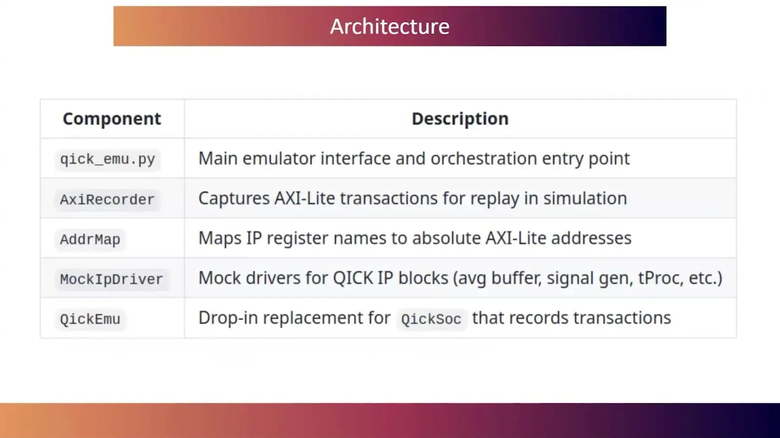
An $18,000 QICK box is cheap for the field but a barrier for students, Oriani said. The emulator’s far end is a fixed 100 nanosecond delay with no model of a qubit behind it, so it teaches the controller with no qubit physics behind it. Cancelo said QICK 2 on AMD’s newer Versal chips is in the works.
Fermilab plans QICK-II with built-in AI engines
Gustavo Cancelo of Fermilab gave the keynote that opened Monday’s Q3-Control workshop, which aimed to produce a white paper and roadmap. Cancelo argued that open designs suit a field with so many qubit types and can still make money, citing Fermilab’s partnership with Qblox. The current QICK box links up to 16 boxes, kept in step to better than 100 picoseconds. Cancelo doubted one box fits all.
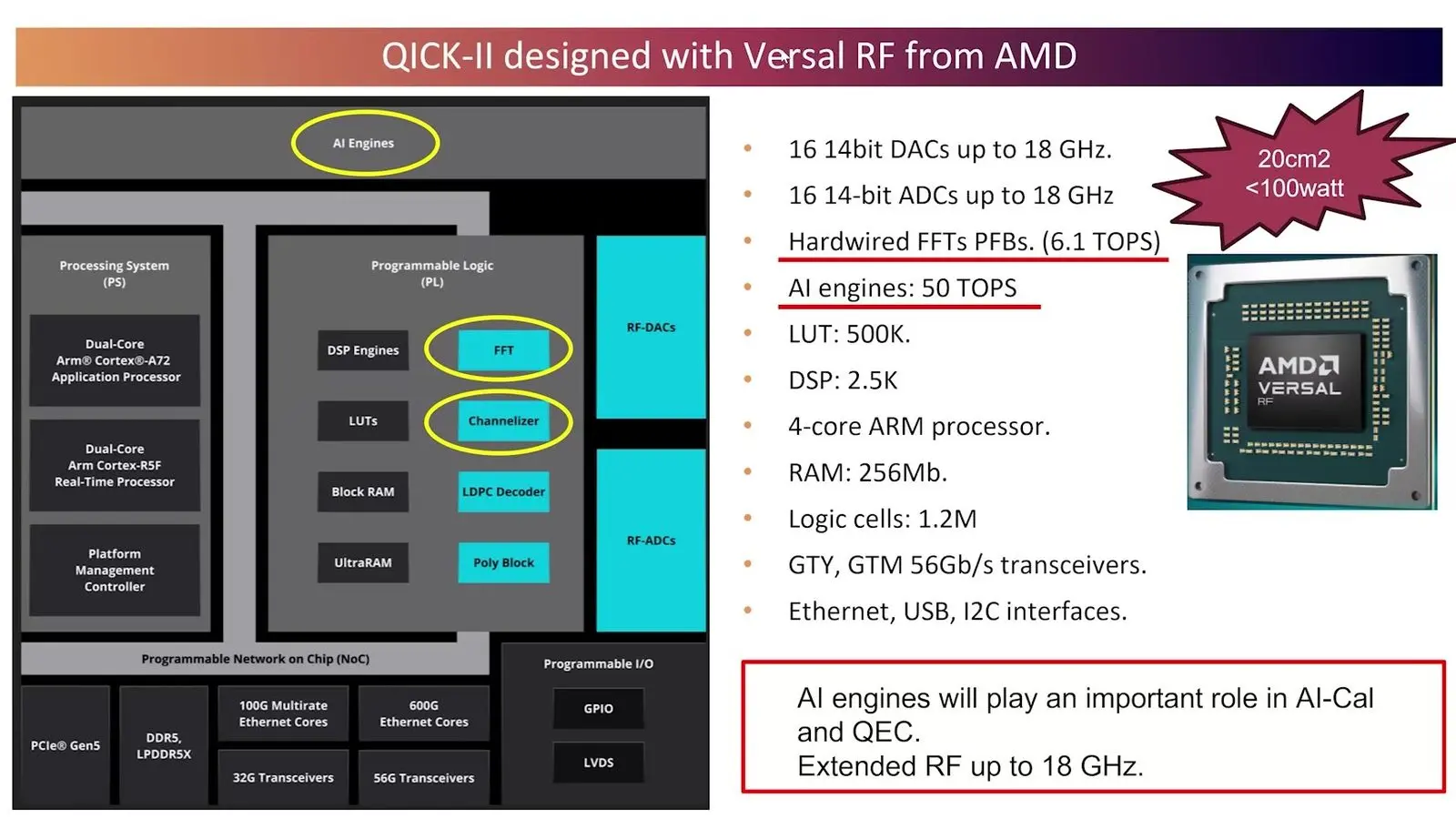
QICK-II is built on a newer AMD chip. It will be faster and will carry its own AI engines. Cancelo wants the chip to sift calibration and error data early, as a trigger throws out dull events in a particle physics experiment before anything reaches a big computer. One recent problem, Cancelo said, needed only a small neural network.
Safran syncs QICK boards with White Rabbit
An engineer from Safran showed how to lock QICK boards to White Rabbit, a fibre network that shares precise time. A closed core on each board takes its clock from the fibre, and two boards under one White Rabbit switch then played a 500 megahertz tone for hours with no visible drift between them. Timing wobble was 6.2 picoseconds.
The sync happens only at the start, with each board waiting for one agreed instant. Resyncing in the middle of a run is left for later.
Nowrouzi moves randomised compiling onto QubiC’s chip
Kasra Nowrouzi, chief technology officer of QuNorth, drew on their years running hardware at Berkeley’s Advanced Quantum Testbed. Nowrouzi argued that quantum computing drew its layered stack first and then tried to build hardware to fit it, when the two should have been designed side by side from the start. Their first example was randomised compiling. It adds random steps around each gate so that errors average out.
In software that took about 500 seconds for a thousand shots on a modest circuit. Every shot needs its own compile. QubiC drew the random choice on the chip itself and finished in about 2 seconds, which is as fast as the plain circuit with no random steps in it at all. Nowrouzi then described QuNorth’s planned machine with Atom Computing and Microsoft, aimed at more than 1,200 ytterbium atoms and early 2027.
The workshop votes against one stack for all qubits
Andrea Delgado ran the second half of the block in Monday’s workshop as a vote on claims for its white paper, with Gustavo Cancelo, Patty Lee of Quantinuum, Jamie Phan of Q-CTRL and a Qblox speaker. The Qblox speaker said the processor itself keeps changing, so a tight join made too early will not fit the next chip. On standards, one voice called a formal document premature. The last claim carried.
A single control stack for every qubit type is a myth, the room agreed, because gate times and channel counts differ by qubit and a shared layer gets harder the closer it sits to the hardware. QICK was offered as the box many labs already bend to their own pulses.
Cancelo recaps the week for the AI meeting
Gustavo Cancelo, speaking on Wednesday, summarised Monday’s workshop for the AI for Quantum Control meeting. In Cancelo’s own view only large firms such as IBM have a route to a full quantum computer, while everyone else works on separate fronts. For that wider group, open source is essential. Opening only a small part of a stack, Cancelo said, is of little use.
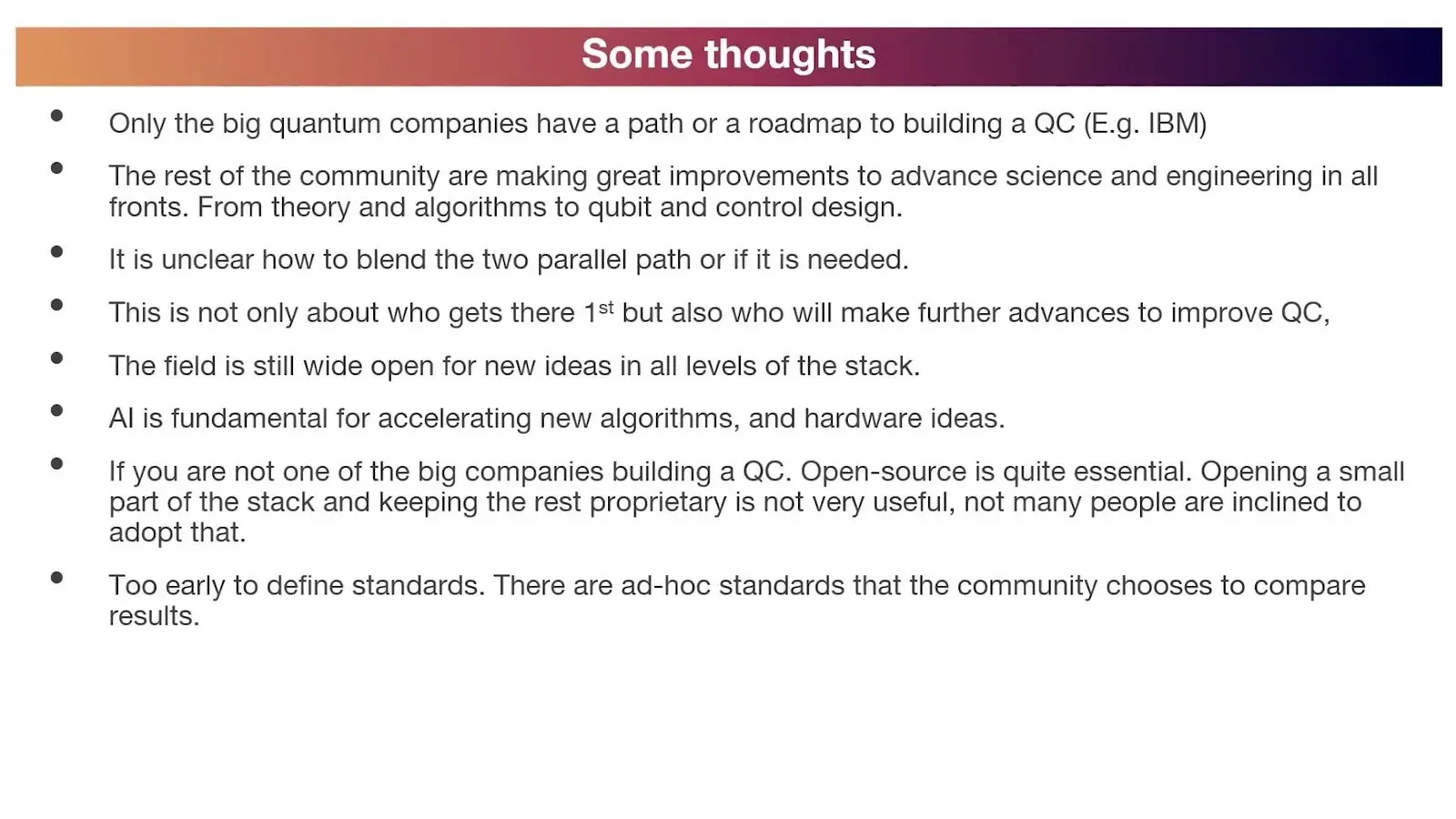
Asked what Cancelo meant by ad hoc standards, Cancelo pointed to the figures labs already compare, such as gate fidelity and link speed. Cancelo closed by saying it is too early for formal ones.
An open brainstorm asks for shared data
The last 40 minutes of the AI for Quantum Control workshop were an open brainstorm. One participant asked for a table of control tasks with their deadlines, an example method and a shared data set. Brandon Severin of Conductor Quantum asked how anyone can test an AI agent whose instructions are plain text, when one added comma can change what it does and nobody can see why. A QuEra speaker told of an agent that found good laser settings it could not relock.
Data took over the end. A member of the QICK team said its emulator makes readout data for one qubit but nothing yet for many. Asked why ideas from workshops rarely reach the controllers people buy, Severin said vendors want to lock customers into their own software.
A second panel expects specialist vendors to build the stack
Kasra Nowrouzi of QuNorth asked Jamie Phan of Q-CTRL, Edward Kluender of Zurich Instruments, Munir Hasan of Riverlane and Niels Bultink of Qblox who should build what. Hasan and Phan expect specialist vendors to take over. Labs build their own stacks today. Kluender said the first large machine will be designed from the bottom up, with flux control moving into the fridge first and decoding staying warm.
On standards Bultink offered three routes, Riverlane’s QECi link, NVQLink and a hard-wired link that no standard can beat. Kluender said standards must wait until data reaches the decoder in under a few microseconds. Calibration split the stage. Bultink said Zurich Instruments’ workflow graphs mostly sit above the box’s job, and Kluender replied that the sweeps already run there.
Michael Sorensen of Atom Computing, whose 1,200-qubit machine must learn to calibrate itself within months, sorted that work into three kinds. Some drifts should be designed out. Other checks can run alongside programs, and a last group of measurements on the atoms must simply be fast.
Languages and compilers for pulses
A quantum program has to be compiled twice, once into gates and again into timed pulses on real wires. Six talks worked on that second step.
Qilimanjaro’s QProgram writes pulses for any rack
Vyron Vasileiadis of Qilimanjaro, a firm in Barcelona, taught the first half of a tutorial on QProgram. It is a free Python language for writing the timed pulses that drive superconducting qubits, and one program can run on a Qblox rack, a QDevil source or a simulator. Today, moving an experiment between labs means rewriting it in each vendor’s own code. QProgram aims to end that.
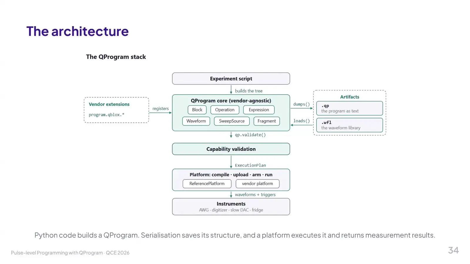
A program is a tree of typed steps, checked against what a platform can do and saved as versioned text. Their longest example was timing. Each signal line keeps its own clock, so without a sync command a long readout starts beside a short pulse and misses the qubit state. Everything ran on the simulator.
The second half adds sweeps and an execution plan
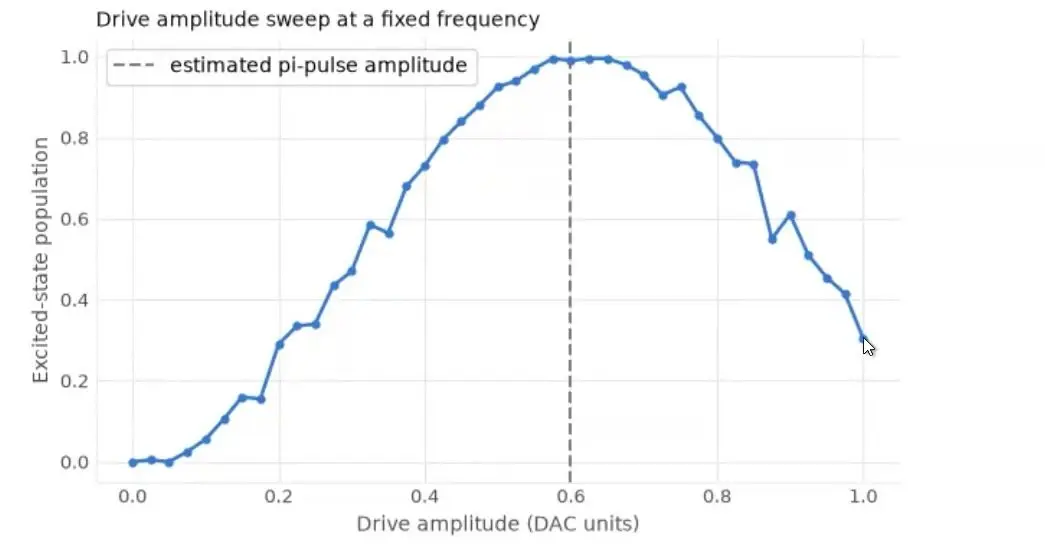
Flavie Le Bars of Qilimanjaro opened the second half with sweeps and averaging. Their simulated scan of 101 frequency points found the resonator dip at the modelled 7.2 gigahertz. Vasileiadis then solved an exercise that finds how strong a pulse must be to flip a qubit, and the run landed close to the model’s value. Both ran on a simulator.
A check marked each step as real time or host. A setting that only the host computer can change forced an average off the controller, so an optimise step swapped the loops and let the average run in real time again. Every result came from the simulator. The hardware runs promised in the abstract were not shown.
NVIDIA’s typed dialect catches pulse errors early
Anthony Santana of NVIDIA presented work with Alex McCaskey, Shane Caldwell and Krysta Svore on a compiler step for programs already turned into pulses. Each drive line and readout line is a resource that a step uses once and hands back, so the order of hand-offs is the schedule. On 250 test programs the checker got every one right, though Santana said it began near 75 percent and the same set was used to find and fix bugs. Loops survive the step as well.
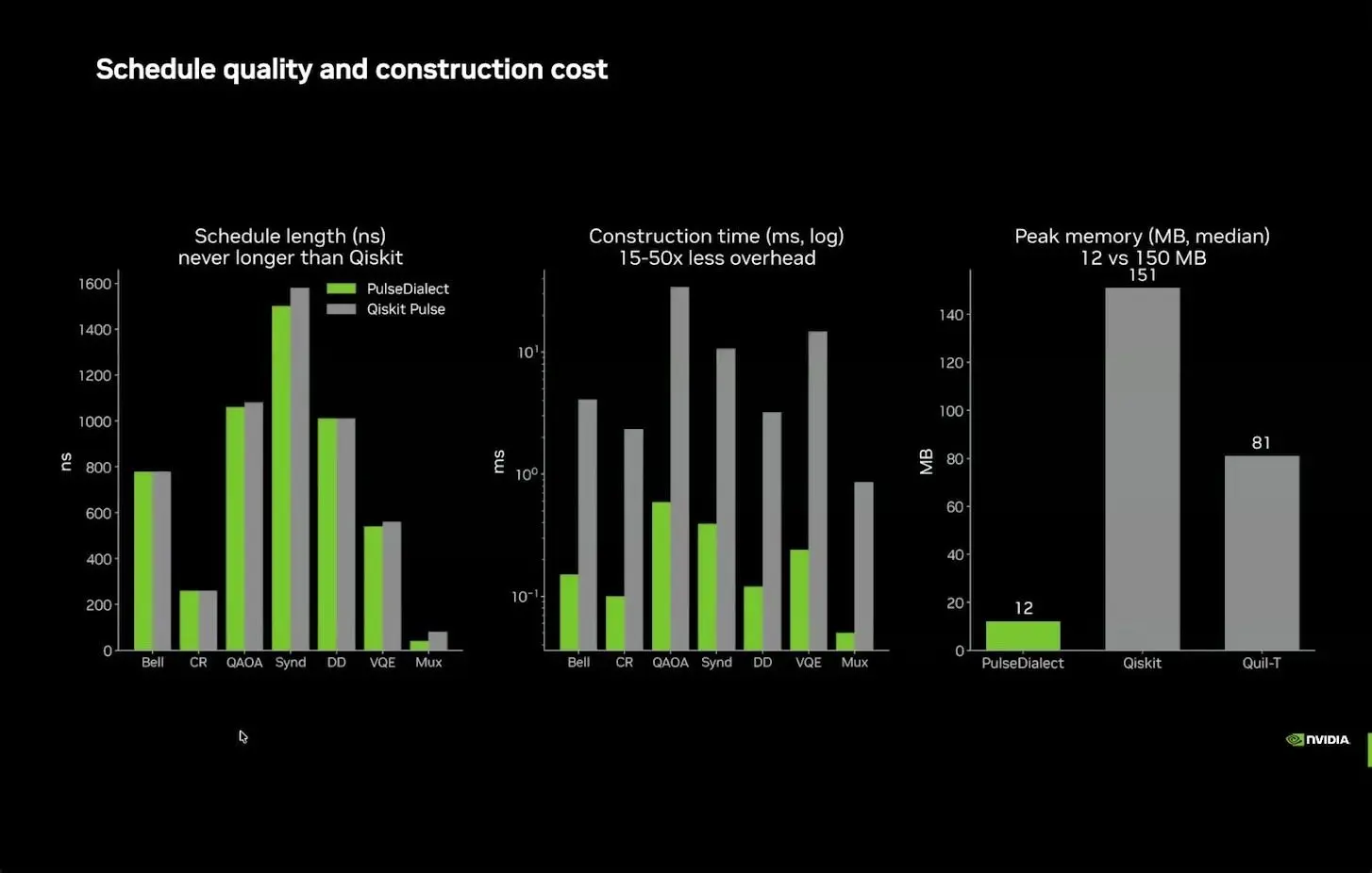
Its schedules were never longer than those from Qiskit Pulse. They were built 15 to 50 times faster, and the tool laid out a surface code of about 8 million qubits in 39 minutes, a size at which Qiskit Pulse had long since timed out. The pulses come from no real device. Santana called the big runs engineering curiosity.
Q-CTRL’s Hyalite joins host code and pulse code
Jamie Phan of Q-CTRL presented Hyalite, a compiler built on the LLVM and MLIR toolkits that treats a classical loop and its pulse schedule as one C++ program. The compiler can then decide what runs on the host computer and what runs on the timed controller. The motivating job is a calibration sweep, where each result must return before the next step is chosen. Splitting that loop across two languages lets the halves drift apart.
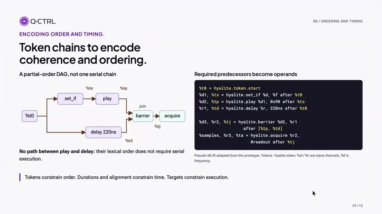
Order in Hyalite is a partial graph, so two steps written one after the other in the code need not run one after the other on the wires unless something links them. Python and OpenQASM front ends are marked as later work.
Qblox says compilers must keep loops intact
Daniel Weigand, technical product manager at Qblox, closed the openQSE workshop on what compiling to control electronics should mean. Weigand argued that a program’s loops must survive, because unrolled loops grow with the square of the qubit count and a million-qubit program will not fit once flattened. Each wire has its own processor. A large machine means millions of threads.
Each message between cores costs about 10 nanoseconds on their cluster and more on a large machine, so a compiler should send it once, at the start. On one shared time grid, Weigand said, cancelling crosstalk becomes a change of numbers that still fits at 100 qubits.
Qblox’s Delgado asks schedulers to use the box’s own computing
Andrea Delgado of Qblox, speaking in a personal capacity, argued that control boxes hold computing power that a scheduler should use with care, in place of sending every signal out over a fast link. The box can do more. A scheduler would decide what runs inside it, what runs on an FPGA and what goes out to a GPU. Delgado called that job resource orchestration, the one most often missed.
Delgado’s example was a form of phase estimation that works one step at a time. A fix worked out in hardware from one helper qubit takes the place of a whole row of extra qubits, so two qubits are enough for any precision. Timing matters too. If gate timing slips, Delgado noted, an algorithm averaged over many runs breaks with no warning.
In questions Delgado said one box that controls 100 qubits draws about as much power as one GPU and fits a standard rack. Qblox publishes its assembly language, which NVIDIA used for a pulse-level representation.
Designing better pulses
The shape of each pulse decides whether a gate works. Eight talks searched for pulses that hit their target and keep working when the hardware is slightly off.
QCSOS certifies a global search for gates
Alexander Leong opened the Sunday morning control block with QCSOS, a way to search for the drive that produces a chosen gate and to check that the search did not stop in the first dip it found. Common methods only look locally, Leong said. Their step shrinks the problem before a solver starts, and symmetry cut the variable count 27-fold on their cases. The solver is Leong’s own.
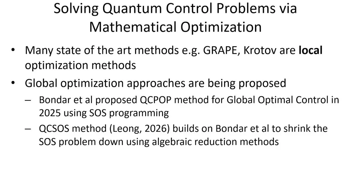
On a three-level test system QCSOS was the quick method, and Leong put the speed gap on their plot at roughly 300 to 500 times. The curve then flattened, and having run only this one problem, Leong would not claim a better floor.
Florida designs the device and the pulse together
A colleague presented this University of Florida paper for Qimao Yang, written with Hanbo Yang and Jing Guo. With one error in every thousand gates, a run of a thousand gates has only about a 37 percent chance of finishing clean, so the device and the pulse should be designed to resist noise together. CORAL picks both at once. It learns by trial and reward.
On two coupled qubits, an ordinary gradient search won when there was no noise. Once noise was added, CORAL finished lowest, and it stayed ahead even when one noise source was five times what it had trained on. Every figure came from simulation.
Chicago finds a common robustness score misleads
Andrew Kamen of the University of Chicago presented work with Samuel Fine, Bikrant Bhattacharyya, Frederic Chong and Andy Goldschmidt. The question is how to score a pulse’s sensitivity to small errors, such as a stray frequency shift. Kamen set three scores side by side and showed that the one Kamen said the field has been minimising parts company with the true value it is meant to track once an optimiser leans on it. A score that tracks the noise with an extra equation stayed on target.
On hardware, with Xuntao Wu and Andrew Cleland, a gate on one qubit reached two to three nines in randomised benchmarking. Pulses trained against a known error lost less fidelity as that error grew. Two-qubit tests are next.
HyPulse stores trapped-ion pulses by hash
Frank Mueller of North Carolina State University presented work with Masoud Hakimi Heris and Yuan Liu on trapped ions, whose shared vibrations can act as an extra quantum memory beside the qubit. Every distinct gate setting needs its own laser pulse, so pulse design is costly. HyPulse optimises each pulse once offline and stores it under a hash of gate, device and model. A retuned trap gets a new hash, so an old pulse can never play on it.
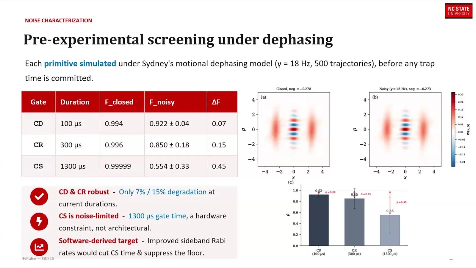
In simulation two gates reached 0.994 and 0.996 fidelity. With the vibration’s phase drifting, which is what real traps do, they fell to 0.922 and 0.850, and a slow squeezing gate fell to 0.554. Hardware tests with Duke are planned.
Fermilab adds buffer levels to cavity training
Oluwadara Ogunkoya of the SQMS Center at Fermilab presented work with Tanay Roy, Doga Kurkcuoglu and Silvia Zorzetti. The hardware is a microwave cavity joined to a qubit, and the data sit in the cavity’s levels. The cavity has endless levels, while a training computer can only model a few, so pulses tuned in that small space can look perfect and then fail in the lab as energy leaks upward. Ogunkoya’s group set out to tame that leak.
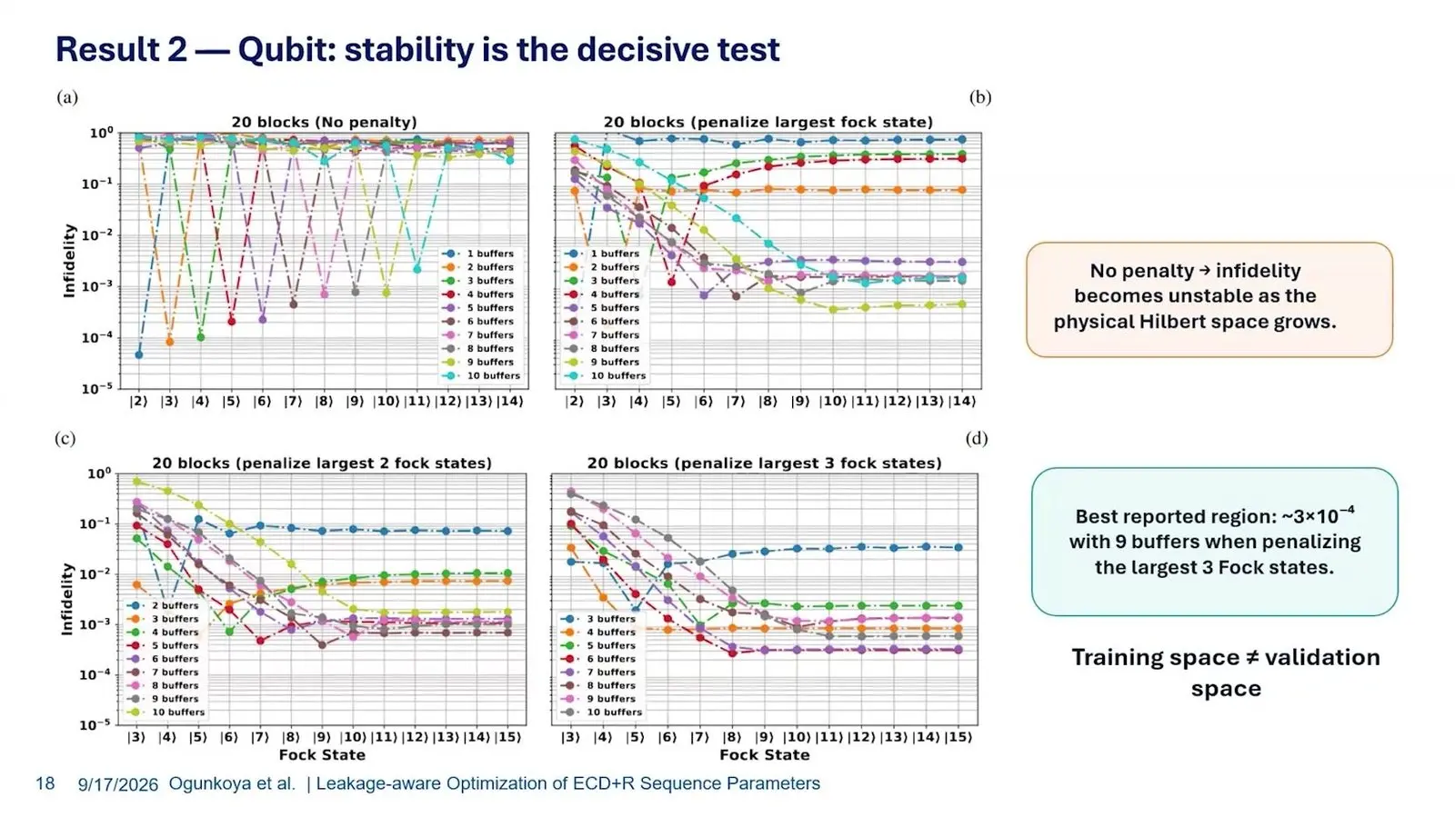
Ogunkoya added spare levels to the training space and a penalty on any energy that reached the top ones. Runs without the penalty swung wildly as more levels were checked, while runs with the penalty levelled off and stayed put however many levels were added. The right number of spare levels depends on the device.
Munich’s drift-tolerant pulses hold up after ten days
Amit Devra of Munich Quantum Valley, who leads its science programme, tested pulses built to survive control error. Decoupling fills a qubit’s idle time with pulses that cancel slow noise. On five IQM qubits a sequence called U-TRACK4 held up where the standard XY4 did worse than leaving the qubits alone, and Devra blamed Gaussian pulses in XY4 that overlapped.
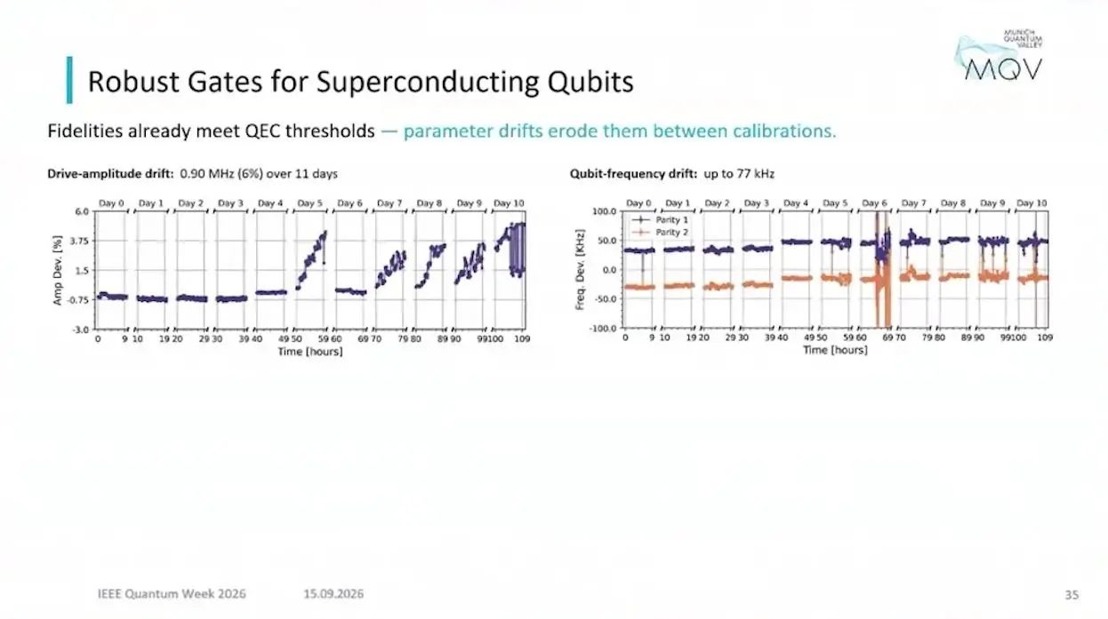
On a superconducting device, drive strength moved by 6 percent over 11 days. Qubit frequency moved up to 77 kilohertz. Two pulse families, both built with GRAPE and average-Hamiltonian theory, were built to ride out that drift. On a WMI device they matched DRAG, a standard pulse shape, on day 0, and by day 10 they held up better than it did.
For neutral atoms, the fastest pulses that avoid recoil ran 20 times faster than the slow sideband drives in the literature. That figure came from a simulation.
NVIDIA’s neural operator halves the pulses for a molecular ion
Taylor Patti, who runs NVIDIA’s group on quantum simulation and AI, reported a search for control sequences on a hydronium ion held beside a calcium ion. A UCLA PhD student drove the work. The tool is a Fourier neural operator, a network that learns a differential equation, and Patti said it returns a million points for the cost of one run.
The search runs 10 strands at once over pulse times and detunings, keeps the best of each round, then follows the operator’s slope to polish the winner. Its sequences used about half the pulses of the best result from reinforcement learning. They also found an answer about 90 percent of the time. The old method managed about 40.
The comparison took seven hours only because the operator ran the simulations for it, Patti said. A full run would have taken about seven months.
QSP-Control cancels a cavity’s Kerr shift at logarithmic cost
Aishwarya Majumdar of North Carolina State University presented QSP-Control, written with John Martyn, Yuan Liu and Nathan Wiebe. Quantum signal processing repeats one fixed step between rotations that can be tuned, so that a circuit of depth d applies a polynomial of degree d to a number hidden in that step. Here the step is the link a qubit and an oscillator have by nature. Gradient methods can stall, Majumdar said.
The first use straightens out a Kerr shift, which depends on how many photons a cavity holds and is fixed once a transmon and cavity are built. A cascade of imperfect rotations mimics the ideal fix up to a cutoff photon number. The cost grows as more levels are fixed.
The second use adds a photon to chosen levels of an oscillator in superposition. Ordinary ladder steps cannot do that, because they act on every level at once. Steps for one level at a time add up in a straight line as levels are added, while one polynomial tuned for all of them grows only with the log of the count. How long the qubit stays coherent limits the depth, Majumdar said, though experiments have reached a few hundred degrees.
Readout and control for ions and atoms
Reading a qubit fast and driving ions and atoms at scale bring their own limits. Seven talks worked on that hardware edge.
Quantinuum ties trap electrodes together
Patty Lee, chief scientist for product technologies at Quantinuum, looked at cold control chips from the trapped-ion side. Quantinuum’s 98-qubit Helios has none, and Lee said the 192-qubit Sol planned for 2027 probably will not either. Each trap electrode needs a precise, quiet and fast analogue voltage, which is costly and crowds the vacuum wall with cables. Quantinuum ties matching electrodes together.
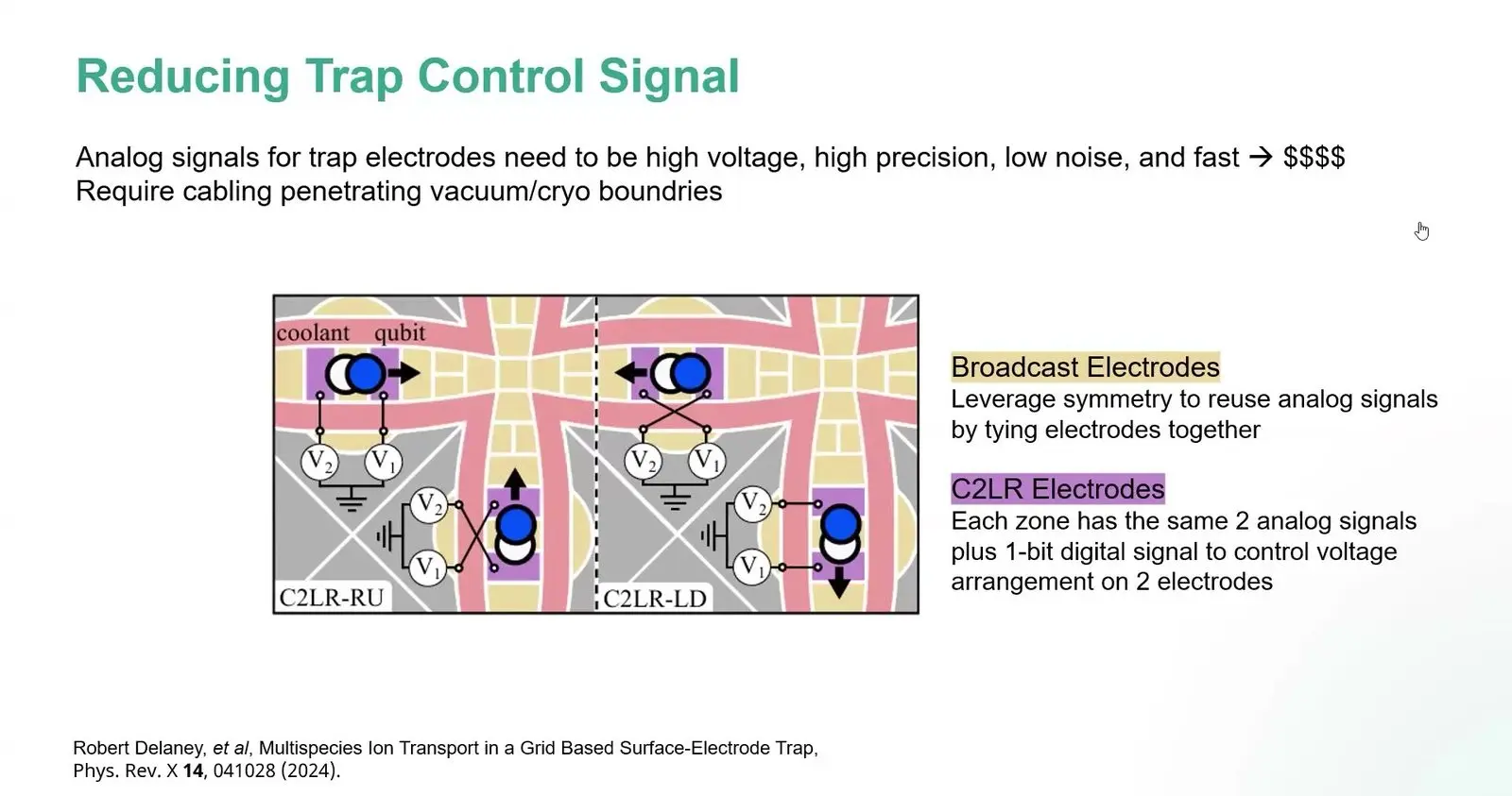
Each zone then gets two shared analogue voltages plus a one-bit digital switch that sends an ion left or right. The number of costly channels then stays fixed as zones are added. Only cheap digital lines grow. Lee said the heat that each channel may give off at 4 to 20 kelvin, where cold control chips would sit, is still unknown.
Sandia’s Octet compresses pulses into tables
Dan Lobser of Sandia National Laboratories presented Octet, the controller behind Sandia’s trapped-ion testbed. Its laser gates need two tones per output and quick jumps in frequency. To cut the data, each pulse is split into short pieces fitted with smooth curves, and repeated gates are stored once in lookup tables so that the board does not hold the same shape twice. A measured result picks the next branch.
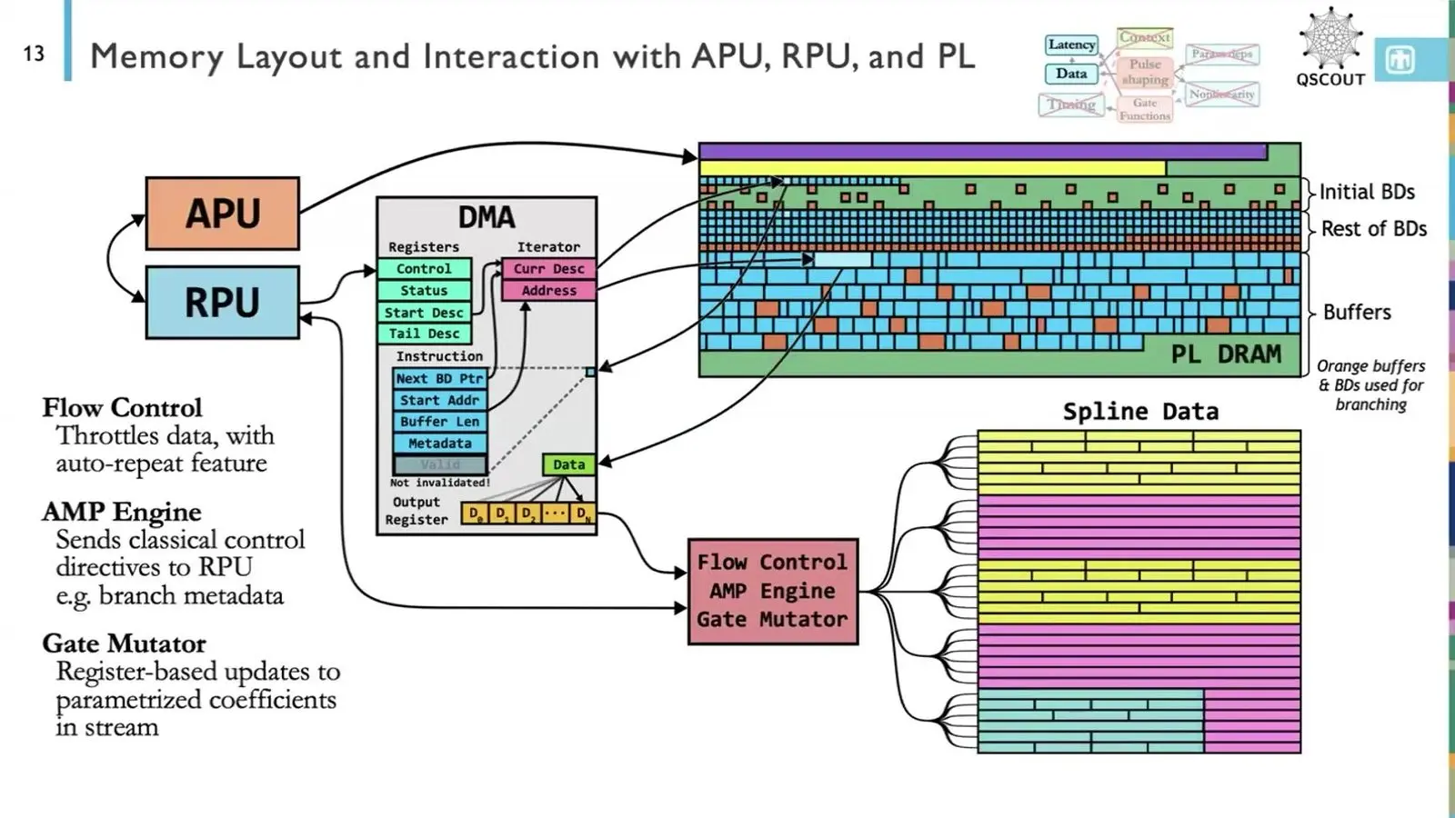
Its memory holds about 10 million distinct gates. In a demonstration, the controller ran an optimiser and updated a gate on every shot, each of which took 1.4 milliseconds from start to finish. Sandia shares the design under licence with groups such as Duke and Waterloo.
AtomFlow takes the host out of the atom loop
Jonas Winklmann of the Technical University of Munich presented AtomFlow, which won a best-paper award in the QSYS track. Neutral-atom machines take a picture of atoms in traps, then sort them into a target pattern, and the loop repeats hundreds of times. AtomFlow puts the camera, the image work, the sorting and the waveform maker on one FPGA. The host computer leaves the loop.
The chip reads and hands off an image in 2.4 milliseconds and sends the first move at about 4 milliseconds, which Winklmann called a 50 percent gain. The design is not yet placed on a chip, and every resource stayed under 30 percent.
A small Mamba model reads five qubits at once
Xiaorang Guo presented for their master’s student Luca Otting, with Emmanouil Giortamis, Benjamin Lienhard, Pramod Bhatotia and Martin Schulz. One shared line reads many qubits, which saves wiring but mixes their signals together, so the model has to pull them apart again and stay small enough for a chip. Mamba keeps its size fixed as the record grows. A second stage checks for qubits that flip mid-read.
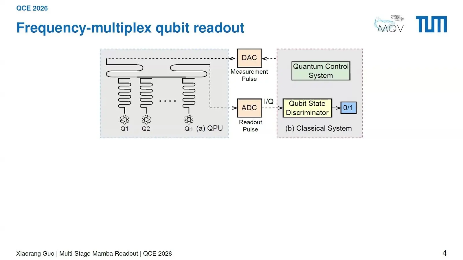
The data are 1.6 million traces from a real five-qubit machine. At 600 nanoseconds the model matched a fidelity that other work reached only at 800, and in a simulated surface code it cut the logical error by 26 percent. The chip has not been built.
An FPGA classifier reads qubits in 1.58 microseconds
Alexis Maya-Isabelle Shuping, an engineer on a Northwestern University and Fermilab team, put a readout classifier onto a chip that can be rewired. Five qubits are read through one shared line, and each must be labelled 0 or 1 within about 2 microseconds, the length of the readout pulse. The first build took 21.69 microseconds. Most of the delay came from streaming samples in.
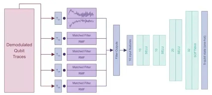
Averaging raw samples, tuning readout length per qubit and packing all five qubits into one wider data packet brought the final classifier to 1.58 microseconds at 90.1 percent fidelity. A run on a real FPGA matched. The group worked from one data set.
Falcon cleans short atom images so correction can cycle at 350 hertz
Swamit Tannu of the University of Wisconsin-Madison works on reading out neutral atoms, where a camera takes a picture of each atom’s glow. That is slow. The gates are much faster, so the time it takes to read sets the clock of the whole machine, and on data from Mark Saffman’s group Tannu showed every classifier failing when short exposures caught only a few photons.

Falcon trains a generative adversarial network, a pair of networks trained against each other, to turn a 1.5-millisecond image into the clean picture a long exposure would give. Cleaning every atom is slow. So a simple template check runs first, and Falcon cleans only the sites where it is unsure. Error correction could then cycle at about 350 hertz at 1 percent readout error, and at 500 hertz at 3 percent.
A standard network needs 3.37 milliseconds of light for the same 1 percent error, more than twice as long as Falcon’s short exposures. Past about 2,000 atom sites the GPU becomes the choke point. Tannu suggested more cameras.
Munich reads transmons at 99.5 percent in 140 nanoseconds
Benjamin Lienhard of TU Munich read transmons at 99.5 percent fidelity in 140 nanoseconds on a better-built chip, by pushing the qubits to higher energy levels during the read. A neural network read five qubits on one line. It beat the usual filters. It also cut crosstalk between nearby resonators about tenfold.
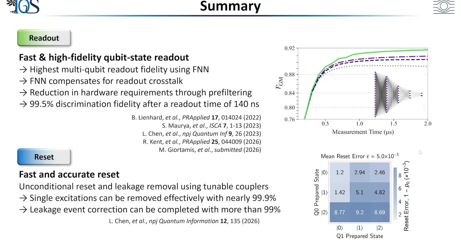
A slimmer version built for FPGAs with Tannu’s team, ten matched filters feeding a small network, matched or beat the large one. For reset, the group swaps a qubit’s energy into a tunable coupler and dumps it into a resonator. The mean reset error was 5.0 thousandths.
Inside the industrial control stacks
Tuesday’s control-systems workshop asked the firms that build whole machines, and one instrument maker, how they drive qubits at scale. Eight of its talks and panels follow here, and they held the week’s largest hardware results.
HRL drives 48 silicon spins from a controller in the fridge
Stephen Carr of HRL Laboratories put an exchange error near 3 times 10 to the minus 4 on 48 silicon spins, driven by a controller that sits in the fridge. The controller holds 70 million transistors and draws 3.5 watts at 4 kelvin. The chip has 54 silicon-germanium quantum dots and up to 18 exchange-only qubits, in which three electrons make one qubit. Once its memory is loaded, Carr said, room temperature sends no important control.
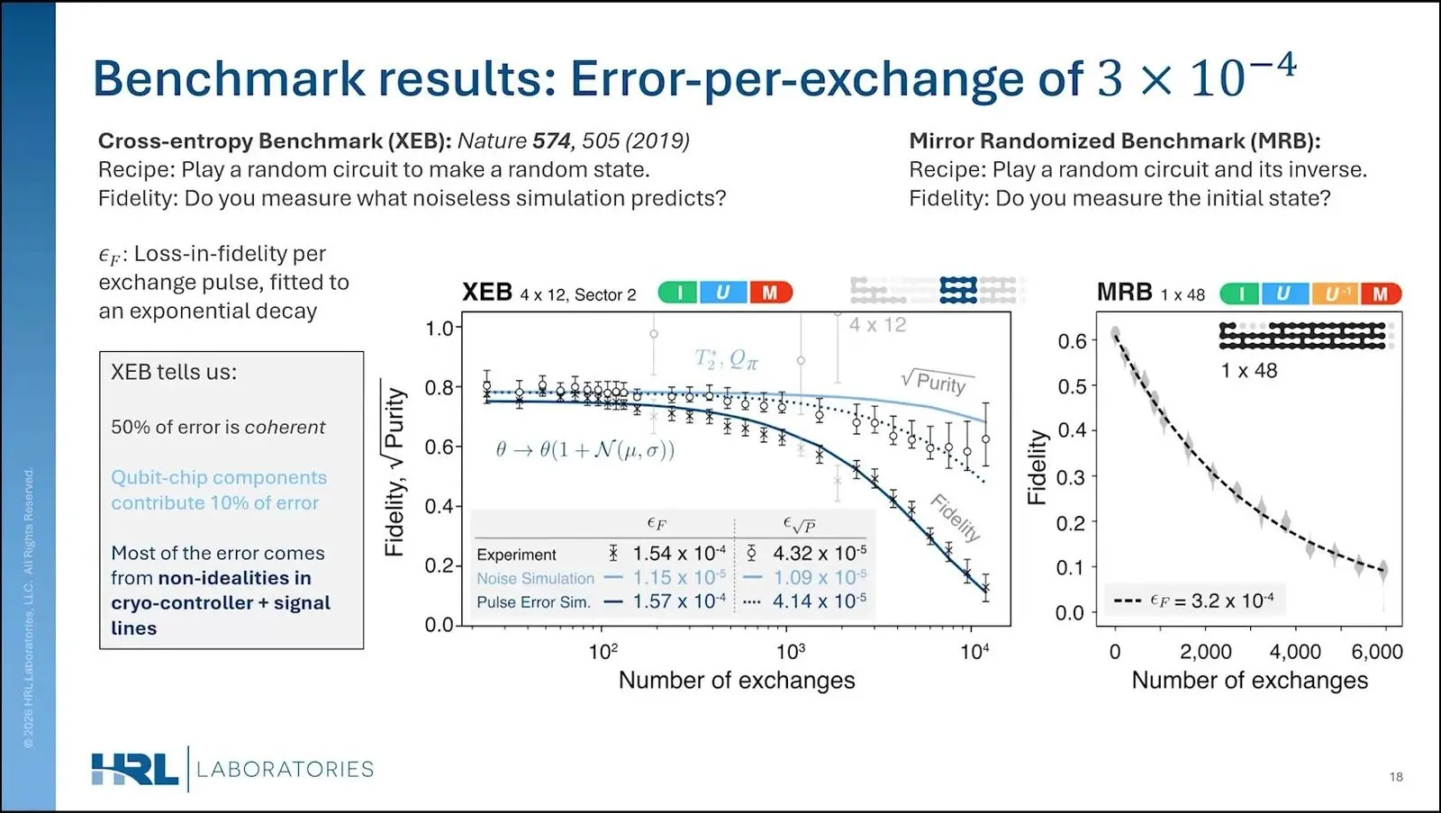
Mirror randomised benchmarking, which plays a random circuit and then its inverse, ran on all 48 spins at once. Carr’s card put half the error down to coherent miscalibration and only 10 percent to the qubit chip, with most of the rest from the cold controller and the signal lines. The chip was the small part. With the controller cleaned up, Carr said, the exchange error could fall to about 1 times 10 to the minus 5.
A two-qubit gate takes about a microsecond. Any decoding would still happen at room temperature. Two larger codes, a distance-9 repetition code on 15 qubits and a surface code on 14 qubits, were still being worked on when Carr spoke in Toronto.
Northrop Grumman sets a correction round at 120 nanoseconds
Dusty Johnson of Northrop Grumman put digital and analogue control in the same package as dual-rail qubits, all of it held at millikelvin. The logic comes from a circuit family the firm has worked on for 15 years. Its design sets the round at 120 nanoseconds. That is about eight times faster than usual, Johnson said, since a round takes a microsecond or so on typical superconducting chips driven by pulsed microwaves.
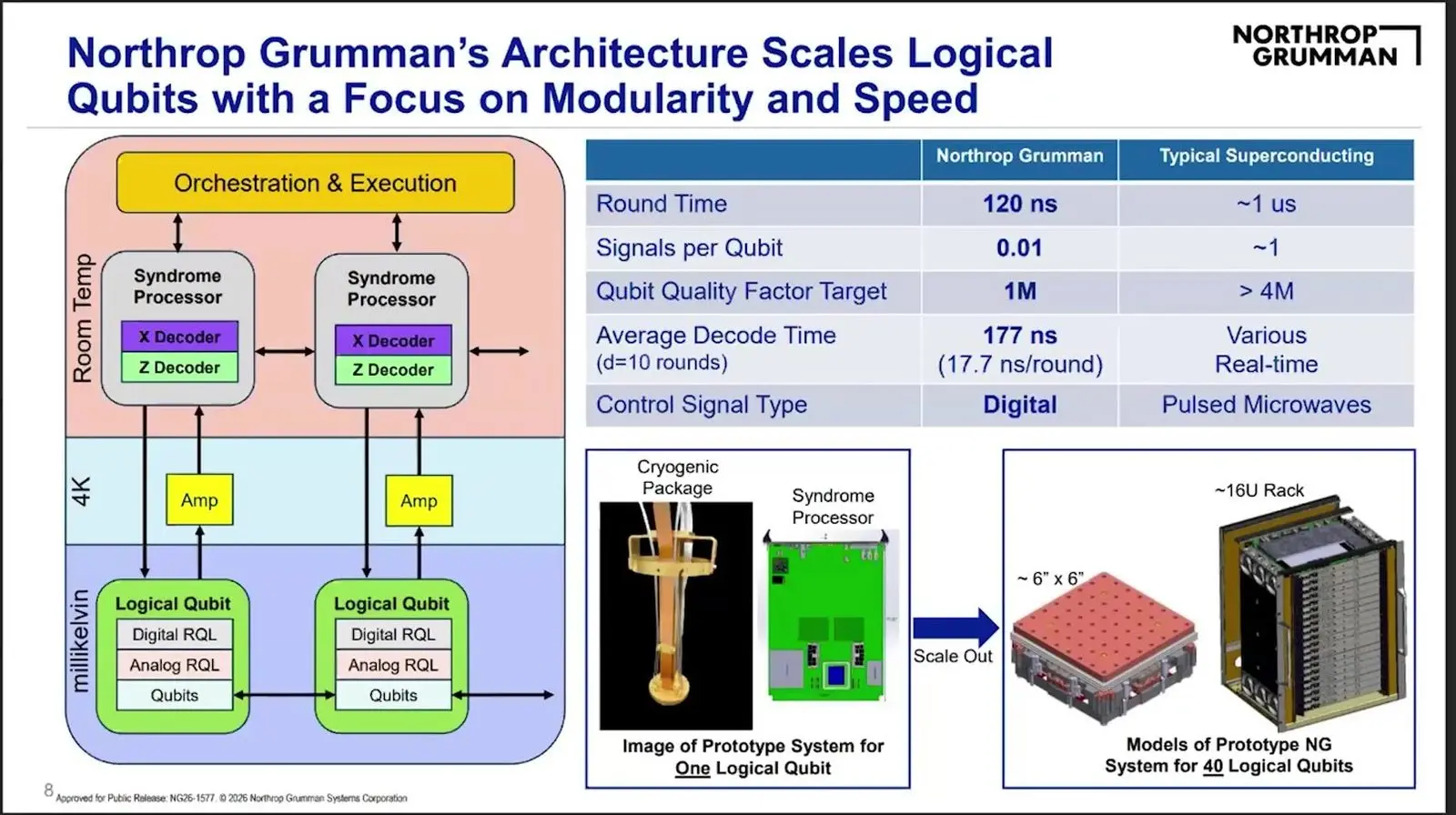
Going from one control signal per qubit to 0.01 is, in Johnson’s terms, a hundredfold cut in cables. The decoder works only on nearby data. It was tried on an FPGA and timed in a custom chip at 1 gigahertz, and a distance-10 decode takes 177 nanoseconds on average. The surface-code gains came from a simulated plot.
The big design, 776 dual-rail qubits on a chip 2 centimetres across, exists only as a design and was never built. Johnson has 122 dual-rail qubits in the lab, a first batch for a threshold-style test.
Atom Computing runs a memory experiment to 90 cycles
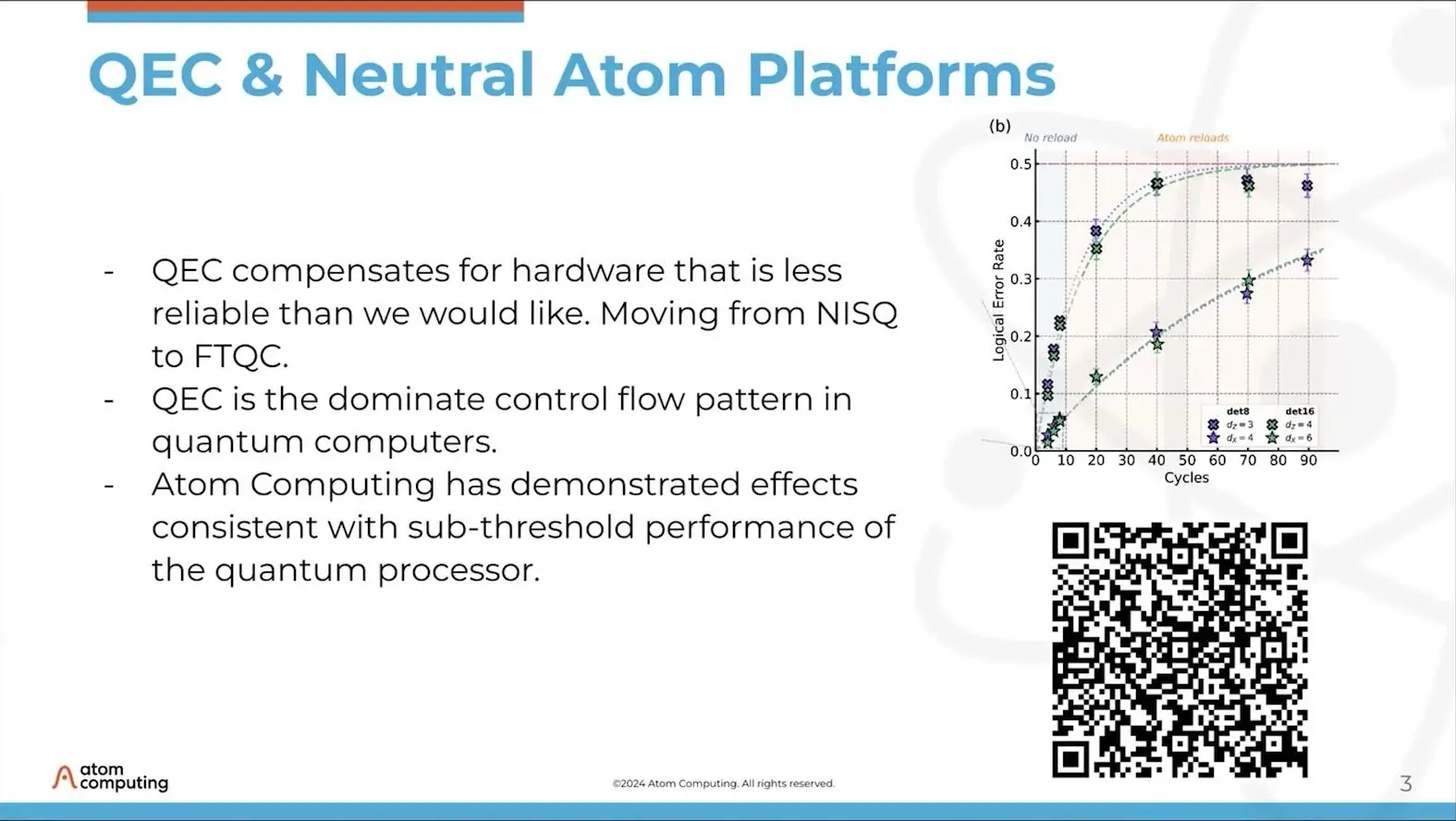
Michael Sorensen of Atom Computing, who heads its software and controls, showed a memory test on the company’s machine of about 1,000 neutral atoms. It ran to 90 cycles. Runs that refilled lost atoms kept their logical data much better than runs that did not, and the slide called the results consistent with work below threshold. Error correction, Sorensen said, is the main control-flow pattern of a quantum computer.
About 200 devices, from lasers and mirrors to cameras, sit under one layer that runs them all. The top layers run Python on ordinary servers. Lower down they need FPGAs and careful handling of memory, and the firm has linked GPU servers to the machine through NVQLink, sending terabits of control data, mostly orders to move atoms, by Sorensen’s account.
IBM packs about 12,000 channels into a rack
Jonathan Kaus of IBM’s quantum instrument control group said IBM’s fourth generation of control boxes handles about 12,000 channels per rack. About 2,400 drive qubits. The rest serve tunable couplers, and the density comes from custom chips, warm ones for microwave drive and planned cold ones for flux, aimed at the Starling machine in 2029.
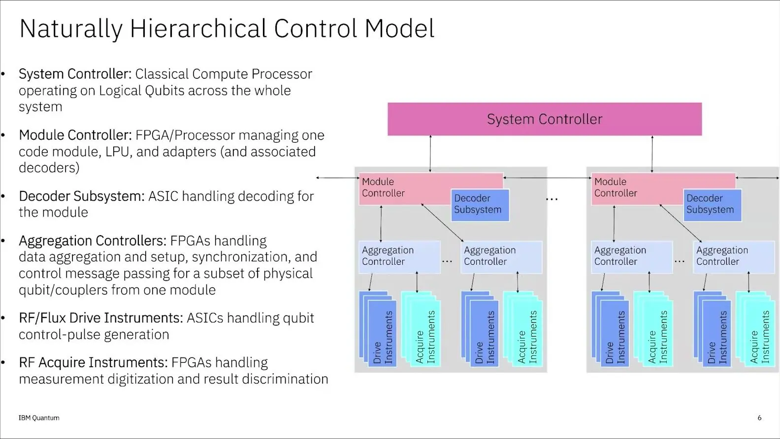
The control model mirrors IBM’s modular machine, whose code modules hold about 12 logical qubits each, and a system controller at the top sees only those logical qubits. Below it, module controllers plan the logic and each runs its own decoder chip. Failed units can be swapped while the rest runs.
Asked about NVQLink, Kaus said its couple of microseconds of latency has not been a perfect match, and IBM has mostly kept to its own links. Most failures, Kaus added, are in room-temperature parts such as converters and regulators, which can be fixed without warming the fridge.
Quantinuum runs Helios on 42 controller cards
Thomas Skripka of Quantinuum said Helios runs on 42 RFSoC controller cards, where the older H2 machine needed only five. The software on the cards settled early. Most change now happens in the compiler for Guppy, the firm’s language, and Guppy FT lets experts write an error-correction scheme that the compiler weaves into a normal program as it runs.
A GPU path runs decoders on an NVIDIA Grace Hopper over a dedicated 10 gigabit network, and the results go to every card at once. The slide gave 40 microseconds of decoding latency. Skripka said a best case near 5 microseconds has since beaten it, though the two pieces still have to be joined.
QuEra lets Claude tune its lasers overnight
Tyler Cochran of QuEra, who works mainly on calibration, said Anthropic’s Claude, hooked up through a hardware protocol, ran hundreds of laser-lock tests overnight. In some cases it beat expert tuning. QuEra aims for about 10,000 physical qubits by 2028.
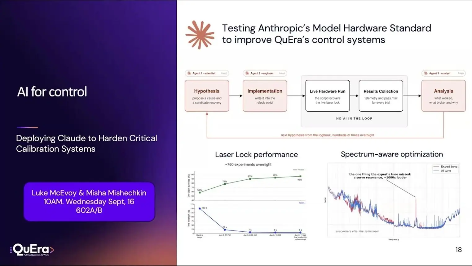
Many neutral-atom operations are global, so one laser pulse can drive gates on every atom that has been moved into place. The software rests on Kirin, an open compiler now being rewritten in Rust. Cochran said that suits AI agents. Programs drop from logical kernels to physical circuits and then to a fixed set of movement lanes, each one tuned in advance of the run.
The machine builders share parts and keep their software
Kasra Nowrouzi of QuNorth asked the four speakers what their companies could share. The atom and ion firms agreed that they use much the same parts, the same chassis and RFSoC boards with GPUs for decoding. Sorensen keeps decoders on GPUs because the error-correction team changes its favourite codes faster than hardware can follow, and Cochran said QuEra will focus on chosen codes to run four or ten times below threshold.
On open hardware, Kaus said IBM’s answer is usually no. It does publish papers on its designs. Skripka said Quantinuum’s hardware and software are too intertwined to separate easily, and when a questioner from HRL asked how fast a new decoder can move into an FPGA, no panellist offered a figure.
Zurich Instruments keeps more than 3,000 channels in step
Edward Kluender of Zurich Instruments presented ZQCS. It keeps more than 3,000 channels in step across up to nine shelves, and three racks of the old generation shrink to a third of one rack. Kluender’s main point was timing, which must stay precise from single gates near a nanosecond to batches lasting a day.
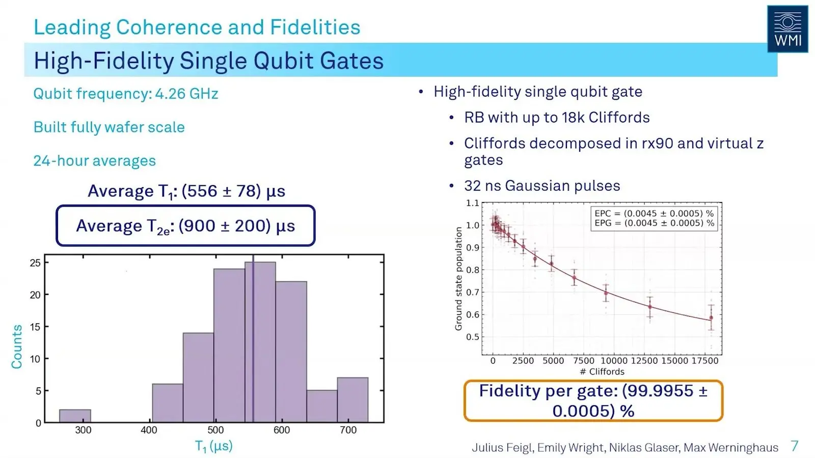
On the current generation, work with the Walther-Meissner-Institute reached a single-qubit fidelity of 99.9955 percent. The test ran out to 18,000 gates. Each shelf has a timing and decoding module with its own FPGA, and a network port that sends data out to CPUs or GPUs for decoding across the whole machine. A tune-up for 200 qubits compiles in under ten seconds.
Machine learning inside the controller
Wednesday’s AI for Quantum Control workshop asked how much learning can fit on the chip beside the pulse generators. Four talks answered in nanoseconds and in shares of the chip.
QubiC’s readout network retrains after every shot
Neel Vora of Lawrence Berkeley National Laboratory showed a readout network that retrains itself on the FPGA after every shot. A test that mimicked the chip on 160 hours of real qubit data lifted one qubit from 93.60 to 96.97 percent. Readout drifts. Retraining on a central computer, Vora said, will not scale to the many thousands of qubits that a large machine will need.

Each guess takes 68 nanoseconds, and the learner updates 32 nanoseconds later, which uses about 64 multiplier blocks per core, roughly 1.2 to 1.3 times as many as the network itself needs. The team has also tried NVQLink with QubiC. It came in at about 4 microseconds.
hls4ml redesigns a QICK readout network in 15 minutes
Nhan Tran of Fermilab said a surrogate model redesigned a QICK readout network on the NERSC supercomputer in about 15 minutes. By hand, the job took months. Tran drew on particle physics, where layers of custom chips, FPGAs and computer farms cut a vast stream of collisions within about 100 nanoseconds, then microseconds, then 100 milliseconds. Quantum control has the same tiers, Tran said.
The tool, hls4ml, turns a trained network from Keras, PyTorch or ONNX into a design for an FPGA or custom chip, with options to shrink number precision and prune weak links. Its companion SNAC-pack uses a surrogate trained on about a million earlier designs to predict chip resources within about 10 percent.
QICK-II will carry 50 TOPS of AI engines
Luis Arnaldi of Fermilab said the standard QICK firmware already fills almost 90 percent of its chip, so room for a neural network has to be cut out of it. The team’s slogan is to bring the AI to the data, by running classifiers inside the FPGA beside the pulse makers.
The next board, QICK-II on AMD’s Versal RF chip, carries 16 converters each way at up to 18 gigahertz and AI engines rated at 50 TOPS, in under 100 watts. Another speaker added that early networks took about 6 percent of the chip, and that newer designs built from lookup tables can fall below 1 percent.
Kolmogorov-Arnold networks learn on an FPGA in 100 nanoseconds
Phil Harris of MIT showed Kolmogorov-Arnold networks, or KANs, learning on an FPGA in about 100 nanoseconds per forward and backward pass while using one to two percent of the chip. A KAN replaces each weight with a learned curve, and the curves are splines that map neatly onto lookup tables. The group’s KANELE paper won a best-paper award from the FPGA community.
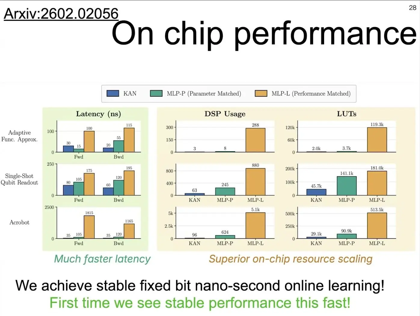
A spline update touches one bin and its neighbours. So learning from one example at a time stays cheap, and it stays stable in the low-precision sums a chip uses, where ordinary networks stall or blow up. On a simulated drifting qubit an ordinary network fell to 50 percent accuracy while the KAN kept track of the drift. Harris put the speed at about a thousand times that of learning on CPUs or GPUs as data arrives.
What it means for buyers of quantum control systems
A lab buying control hardware should ask for a loop time measured on real qubits with real decoding. It should also ask who else can program the box. The talks agreed on the deadline, on moving calibration off the host computer and onto the controller, and on GPU links of a few microseconds.
They disagreed on how open the controller should be. Most hardware runs behind it used small devices. The two large ones came from HRL and Atom Computing, which build their own qubits, and the claims about much bigger machines rest on guesses that no talk put to the test. For the decoders these boxes feed, see our story on Riverlane’s interface on Altera FPGAs and on NVIDIA’s calibration model.
Ben-Shach’s ten microseconds shaped the week, and several vendors in Toronto claimed loops inside it. Those claims were made mostly in emulation, on loopback cables and on synthetic data, and most hardware runs that did exist used devices of a few qubits. The stopwatch is still waiting for the qubits.
- Quantum Machines expands with a second European buy in six weeks
- NVIDIA’s quantum calibration model works across six qubit modalities
- NVIDIA GPUs accelerate quantum error correction calibration
- Alice & Bob tests quantum decoding with Quantum Machines
- Altera FPGAs now support Riverlane’s error correction interface
Frequently asked questions
What is quantum control?
Quantum control is the set of electronics and software that turns a quantum program into precisely timed pulses, reads the qubits back and keeps them tuned. Each gate becomes a shaped burst of microwaves, laser light or voltage. At QCE26 much of the work aimed to make these systems fast enough for error correction.
Why does error correction need such fast control?
Error correction reads helper qubits, works out what went wrong and sends back a fix before the qubits lose their state. On superconducting chips that loop has only microseconds. Gilad Ben-Shach of Quantum Machines set a budget of about 10 microseconds at QCE26.
What is qubit calibration?
Calibration measures each qubit’s properties and retunes its pulses, because qubits drift over hours. On a large chip it can take hours and takes the machine offline. At QCE26 Qblox showed a single-qubit tune-up run on its controller in 286 milliseconds, against 5,520 the usual way.
What is QICK?
QICK, the Quantum Instrumentation Control Kit, is an open-source qubit controller from Fermilab built on AMD’s RFSoC chip. Its team counted 86 papers using it. At QCE26 Fermilab showed a laptop emulator for it and plans for QICK-II on AMD’s Versal chips.
What is NVQLink?
NVQLink is a link from NVIDIA that any control vendor can add, so a GPU can join the feedback loop and decode errors or correct drift while a circuit runs. At QCE26 it appeared in at least five talks, with round trips of a few microseconds.
What happened at IEEE Quantum Week 2026?
IEEE Quantum Week 2026, also called QCE26, ran from 13 to 18 September at the Metro Toronto Convention Centre. This guide covers 55 of its talks on control, calibration and readout, from vendor keynotes by Quantum Machines and Qblox to open-source tutorials from Fermilab.
This guide is based on 55 talks, tutorials, keynotes, workshop sessions and panels at IEEE Quantum Week 2026 (QCE26), held at the Metro Toronto Convention Centre from 13 to 18 September 2026, and on the published conference programme. Names follow the programme. Affiliations and titles not listed there are as speakers gave them. Results are stated as each speaker presented them, and many come from simulation, emulated qubits or loopback tests. Company claims are the companies’ own.
- Qubit hardware and scaling roadmaps
- Photonics and quantum sensing
- Quantum error correction and decoders
- Fault-tolerant compilation and magic states
- Modular and distributed quantum computing
- Quantum computers in supercomputing centres
- Compilers, circuit synthesis and languages
- AI and language models for quantum software
- Testing and reproducible quantum experiments
- Benchmarks, error mitigation and quantum advantage
- Quantum state preparation, oracles and arithmetic
- Quantum optimisation, QAOA and annealing
- Quantum machine learning
- Chemistry, materials and life sciences
- Differential equations and fluid dynamics
- Power grids and energy
- Quantum finance
- Logistics, climate, databases and games
- Quantum networks and key distribution
- Quantum security and post-quantum cryptography
- Quantum education and workforce
- Policy, standards and the quantum business



See today’s quantum computing news on Quantum Zeitgeist for the latest breakthroughs in qubits, hardware, algorithms, and industry deals.